You can start a command by clicking on an icon in a Toolbar or Toolkit and then choosing options in a dialog box or by responding to the prompts displayed on the Command Line.
To see more detailed information about a command, click on the hyperlink.

The following Menu Bar commands only appear in the main menu bar and not in any other Toolbar or Toolkit. Any redundant commands that do appear in Toolkits or Toolbars will be included in those tables.
|
Mode |
Button |
Menu Location |
Command |
|---|---|---|---|
|
All |
|
Creates a new AGi32 file from a previously saved AGi32 Template. |
|
|
All |
|
File - Save As |
|
|
All |
|
|
|
|
All |
|
|
|
|
All |
|
|
|
|
All |
|
|
|
|
Reports |
|
Shortcut: Ctrl - V |
|
| Reports | Reports - Viewport - Hide Viewports | ||
|
Model |
|
|
|
|
Model |
|
|
|
|
Model, Reports |
|
Translate a point to the center of the screen. |
|
|
Model, Reports |
|
Zooms in on a selected point and translates it to the center of the screen. |
|
|
Model, Reports |
|
Enlarge the size of entities in the current view by the current Zoom In factor. |
|
|
Model, Reports |
|
Reduce the size of entities in the current view by the current Zoom Out factor. |
|
|
Model, Reports |
|
|
|
|
Model |
|
|
|
|
Model |
|
|
|
|
Model |
|
|
|
|
Model |
|
|
|
|
Model |
|
|
|
|
Model |
|
|
|
|
All |
|
|
|
|
All |
|
|
|
| All | Tools - Roadway Standards | ||
|
All |
|
|
|
|
All |
|
|
|
|
All |
|
Tools - Update User Information |
|
|
All |
|
Help Menu |
|

The Common Toolbar provides file management, view functions, and evaluation tools for your use.
Some commands are not available in all modes; check the Mode column to see when a command is active.
|
Mode |
Button |
Button Name |
Command |
|---|---|---|---|
|
All |
|
Create a new job file. |
|
|
All |
|
File - Open |
Open an existing AGi32 file. |
|
All |
|
Import a CAD, LaiDex or AGi32 file into the existing file. |
|
|
Model, Render |
|
Exports a CAD file in Model mode. Export an image in Render mode. |
|
|
All |
|
Save your file. |
|
|
All |
|
Print the current view. |
|
|
Model, Render |
|
Copies contents of current View to Windows Clipboard. |
|
|
All |
|
Undo the last command. |
|
|
All |
|
Redo the last command. |
|
|
Model, Reports |
|
Redraw the current view. Redrawing clears any 'ghosts' or blips left behind. |
|
|
Model, Reports |
|
Pan with the mouse using two points of reference |
|
|
Model, Reports |
|
Enlarge an area of interest on your screen. |
|
|
Model, Reports |
|
Size the overall drawing to fit within the confines of the current view with a ¼” border added. |
|
|
Model |
|
Update the view to display the coordinate window defined by the View-Set Limits command. |
|
|
Model, Reports |
|
Return to the previous viewpoint. |
|
|
Model, Render |
|
Display a 2D birds eye view of the environment. |
|
|
Render |
|
Look through the bottom plane of the rendered environment. |
|
|
Render |
|
Look through the left plane of the rendered environment. |
|
|
Render |
|
Look through the right plane of the rendered environment. |
|
|
Render |
|
Look through the front plane of the rendered environment. |
|
|
Render |
|
Look through the back plane of the rendered environment. |
|
|
Model |
|
Specify a viewpoint looking at the environment from the side (through the Z elevation). |
|
|
Model |
|
Specify a viewpoint looking North by specifying the viewpoint location. |
|
|
Model |
|
Specify a viewpoint looking South by specifying the viewpoint location. |
|
|
Model |
|
Specify a viewpoint looking East by specifying the viewpoint location. |
|
|
Model |
|
Specify a viewpoint looking West by specifying the viewpoint location. |
|
|
Model |
|
Display a Room or Object wall or side surface by selecting that surface. |
|
|
Model |
|
Specify a 3D view using the default Isometric View parameters in System Settings. |
|
|
Model, Render |
|
Display a 3D view looking from the North West viewpoint. |
|
|
Model, Render |
|
Display a 3D view looking from the North East viewpoint. |
|
|
Model, Render |
|
Display a 3D view looking from the South East viewpoint. |
|
|
Model, Render |
|
Display a 3D view looking from the South West viewpoint. |
|
|
Render |
|
Cut away the environment from front to back. |
|
|
Render |
|
Move through the environment in the view direction. |
|
|
Render |
|
Move around the environment keeping the same focus point. |
|
|
Render |
|
Move through the environment with Rotate and Pan capabilities. |
|
|
Render |
|
Move left/right or up/down relative in the environment. |
|
|
Render |
|
Look left/right and/or up/down while staying in a fixed position. |
|
|
Render |
|
Enlarge or reduce the graphic size, maintaining the same position. |
|
|
Model, Reports |
|
Interactively pan the display using the mouse wheel button (this command is always active). |
|
|
Model, Reports |
|
Interactively zoom in/out using the mouse wheel button (this command is always active). |
|
|
Model |
|
Interactively set/change the isometric view using the Shift key and the mouse wheel button (this command is always active). |
|
|
Model, Render |
|
Create and manage multiple views. |
|
|
Render |
|
Change the properties of the current view (background color, projection, etc.). |
|
|
Render |
|
Modify the display parameters used in Render mode (display type, color, scaling, etc.). |
|
|
Model, Reports |
|
Measures the area and perimeter for a user defined polygon. |
|
|
Model, Reports |
|
Measures the length between two points. |
|
|
Model |
|
Identifies an AGi32 entity and describes how to modify it. |
|
|
Model |
|
Locates calculated points by value. |
|
|
All |
|
Provides access to customizable settings in AGi32. |
Viewpoints Toolbar

The Viewpoints Toolbar provides the ability to Add Viewpoints, Update Viewpoints, Delete Viewpoints and select Viewpoints for display.
| Mode |
Button |
Button Name |
Command |
|---|---|---|---|
| Model, Render |
|
Contains a list of current Viewpoints in either Model or Render modes. Model and Render Viewpoints are set separately. |
|
| Model, Render |

|
Viewpoint Arrows | Moves between Viewpoints in succession. |
| Model, Render |

|
Viewpoint Delete | Deletes existing Viewpoints. |
| Model, Render |

|
Viewpoint Update | Updates an existing Viewpoint. |
| Model, Render |

|
Viewpoint Add | Adds Viewpoints with autoname or enter your own name. |

The Control Bar provides access to the interface Modes, design tools, and calculation settings.
|
Button |
Button Name |
Command |
|---|---|---|
|
|
Model Tab |
Model Mode provides the interface for simulating the lighted environment. Model Mode is the default interface shown. When Model Mode is current, the Model tab is white and the Render and Reports tabs are tabbed to the background. |
|
|
Render Mode allows you to view, navigate and customize your visualizations. When Render Mode is current, the Render tab is white and the Model and Reports tabs are tabbed to the background. |
|
|
|
Reports Mode provides custom report creation for printing. When Reports Mode is current, the Reports tab is white and the Model and Render tabs are tabbed to the background. |
|
|
|
Design Tools: |
When AGi32 is first initialized, the Room Estimator
Design Tool is the default option. Click on the pull-down arrow to see
the tool selections. The last selected Design Tool will be displayed as
the default option. Roadway Optimizer provides a design tool for optimizing pole spacings along a roadway using various roadway standards and criteria. Room Estimator provides a zonal cavity design tool for estimating illuminance or luminaire quantity in empty rectangular rooms. |
|
|
Enable and specify daylight conditions for a single date and time. Available from pull-down menu: |
|
|
|
Generates ray trace image using current Ray Trace Parameters. Click on the pull-down arrow to see the Tool selections. Available from pull-down menu:
|
|

|
Subdivision | The Subdivision button serves as a toggle, switching the Adaptive Subdivision process on and off. When depressed, Adaptive Subdivision is enabled. You can change the settings for Adaptive Subdivision from the Set Parameters selection in the menu. |
|
|
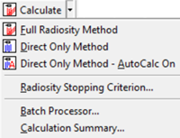
Calculate the lighting effects in the environment and select which calculation method to use for computations. Calculation methods available from pull-down menu: Full Radiosity (Direct + Indirect Light), Direct Only, or Direct Only - AutoCalc On. Also available from pull-down menu: |
|
|
|
Manage and create projects. Available from pull-down menu: Transfer Entity - Single, Window or All selection methods. |
|
|
|
|
Display all defined projects. The default project name is Project_1. |
|
|
Create Scenes based on luminaire dimming and switching strategies. Select current Scene from menu. |

The Status Bar provides access to common System Settings and displays global parameters for the environment.
Some commands are not available in all modes; check the Mode column to see when a command is active.
|
Mode |
Button |
Button Name |
Command |
|---|---|---|---|
|
All |
|
Toolkit Display |
Toggles the Toolkits On and Off, to the last specified location. |
|
All |
|
Statistics Display |
Toggles the Statistics Display On and Off, to the last specified location. |
|
All |
|
Hint Display |
Toggles visibility of the Hint display on and off, to the last specified location. |
|
Model, Render |
|
Add, manipulate and control visibility of Background Images. |
|
|
All |
|
Change the current Display (length) and Illuminance units. Icon displays the current units. |
|
|
Model |
|
Enter values for Design Isolines, enable and disable. |
|
|
Model, Reports |
|
Modify the cursor snap precision. The Snap text box is transparent. Snap button toggles Snap On and Off (F9 shortcut) |
|
|
Model, Reports |
|
Toggling Ortho On restricts the cursor movement to purely horizontal and vertical movement. This mode assists in creating linear environments and placement of luminaires, objects within. Ortho button toggles Ortho On and Off transparently (F8 shortcut) |
|
|
Model |
|
Snap to the endpoints of other entities (drawing entities, objects, rooms) when creating the environment. (F3 shortcut) |
|
|
Model, Reports |
|
Indicates whether the display and statistical entities are current. |
|
|
Render |
|
Toggles textures applied to surfaces On and Off. (F10 shortcut) |
|
|
Render |
|
Toggles the wireframe overlay On or Off. Wireframe overlay indicates the Radiosity (element) meshing applied. (F11 shortcut) |
|
|
Render |
|
Toggles the Model Mode entities to display on top of the Rendered environment. Click on the pull-down arrow to change the Settings or use the Display Properties command. Model Overlay uses a WYSIWYG approach (all entities in Model Mode are visible by default). (F7 shortcut) |
|
|
Render |

|
Toggles the display from RGB color to Pseudocolor's last known setting in Render-Display Properties. Drop down menu provides access to Display Properties to set parameters for pseudocolor display. |
|
|
Render |
|
Anti-aliasing can be applied automatically to the current image when ever navigation stops by depressing the button. Then select an Anti-Aliasing Sampling Level from pull-down list. (F6 shortcut) The Anti-Aliasing Sampling Level indicates the number of image copies applied and offset from the original image in order to provide the appearance of smoother edges (instead of jagged edges). The Default level is None indicating no anti-aliasing is applied by default. The Maximum Sampling Level is 15. Higher sampling levels increase the image quality but also take longer to produce (up to several seconds). An Anti-Aliasing setting of 8 is recommended for most environments. |
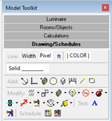
Drawing/Schedules Toolkit
|
The Drawing/Schedules Toolkit allows you to add and modify drawing entities (lines, circles, text) and schedules in your environment. Some buttons have multiple commands associated with them, which are available from the arrow to the right of the button. The secondary options are displayed below the correlated button. The default operation of a button click will be displayed in the menu with the icon adjacent to the command. |
|
Button |
Drawing/Schedules Button Name |
Command |
|---|---|---|
|
|
Modify the current drawing entity line width. The default line width is 1 Pixel. |
|
|
|
Modify the current drawing entity line type. |
|
|
|
Line Color |
Modify the current drawing entity line color. |
|
|
Creates an arc. |
|
|
|
Creates an axis in the X, Y or Z direction. |
|
|
|
Inserts a previously defined block. |
|
|
|
Creates a circle. |
|
|
|
Creates a cube. |
|
|
|
Creates a dimension line in the X, Y or Z plane. |
|
|
|
Creates a line. |
|
|
|
Creates a rectangle. |
|
|
|
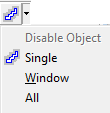
Copy drawing entities into a rectangular grid. The default option is a single selection. Use the secondary menu to select Window or All. |
|
|
|
Copy drawing entities to other locations. The default option is a single selection. Use the secondary menu to select Window or All. |
|
|
|
Creates a global block from the selected entities. The block is accessible from any job file. The default option is a single selection. Use the secondary menu to select Window or All. |
|
|
|
Create Drawing Luminaire Symbol |
Creates a luminaire symbol to use in Model Mode from the selected entities. The default option is a single selection. Use the secondary menu to select Window or All. |
|
|
Deletes the selected drawing entities, including schedules. The default option is a single selection. Use the secondary menu to select Window or All. |
|
|
|
Explodes a block or text entity into individual components (drawing entities or text lines). The default option is a single selection. Use the secondary menu to select Window or All. |
|

|
Mirrors drawing entities using Single, Window, or All selection methods. The default is the Single selection method. |
|
|
|
Move drawing entities (including schedules) to another location. The default option is a single selection. Use the secondary menu to select Window or All. |
|
|
|
Change the color and/or line type of the selected drawing entities. Does not operate on Schedules. The default option is a single selection. Use the secondary menu to select Window or All. |
|
|
|
Rotate the selected entities. The default option is a single selection. Use the secondary menu to select Window or All. |
|
|
|
Scale the selected entities. The default option is a single selection. Use the secondary menu to select Window or All. |
|
|
|
Create text or insert text files into your job file. |
|
|
|
Modify the properties of the selected text. |
|
|
|
Create a dynamic schedule that extracts information about your job file. |
|
|
|
Modify the properties of the selected schedule. |
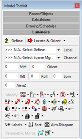
Luminaire Toolkit
|
The Luminaire Toolkit provides access to the add and modify luminaire commands. Some buttons have multiple commands associated with them, which are available from the arrow to the right of the button. The secondary options are displayed below the correlated button. The default operation of a button click will be displayed in the menu with the icon adjacent to the command. |
|
Button |
Luminaire Button Name |
Command |
|---|---|---|
|
|
Creates the internal catalog of luminaires available in your job file. |
|
|
|
Places luminaires into the job file using the current settings in the toolkit and specifies how the luminaire is positioned. Locate - each click drops a luminaire with angles specified in the toolkit. Locate & Orient - first click drops the luminaire at the cursor position, second click sets the Orient angle. Locate & Aim - first click drops the luminaire, second click sets the aiming point. |
|
|
|
Choose luminaire label from Defined Luminaire List |
|

|
Channel | Choose luminaire channel from the list of channels defined in Scene Manager |
|
|
Specifies the luminaire insertion point Z-elevation. |
|
|
|
Apply aiming parameters manually before positioning. |
|
|
|
|
Specify the aiming point elevation. |
|
|
Dynamically array a luminaire or luminaire group with rectilinear options. This is the default option. |
|

|
Array a luminaire or luminaire group along a line either drawn in AGi32 or imported from CAD. |
|
|
|
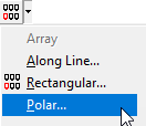
Array a luminaire or luminaire group into a circle or arc pattern. |
|
|
|
Change the luminaire mounting height using the same aiming angles. The default option is Single. Using the secondary menu, you may select Window or All . |
|

|
Change Mounting Height | Change the luminaire mounting height using the same aiming points. The default option is Single. Using the secondary menu, you may select Window or All . |
|
|
Copy luminaires to other locations. The default option is a single selection. Use the secondary menu to select Window or All. |
|
|
|
Delete luminaires. The default option is a single selection. Use the secondary menu to select Window or All. |
|
|
|
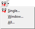
Edit luminaires to change their properties in a tabular fashion. The default option is a single selection. Use the secondary menu to select Window or All. |
|
|
Swap Luminaire Type | Change the luminaire type (Label) using single, window or all selections. The default is single. |
|
|
Move selection set of luminaires maintaining the existing aiming angles. Aiming points will change as luminaires shift position. |
|
|
|
Move selection set of luminaires maintaining the existing aiming points. Aiming angles will change as luminaires shift positions to maintain aiming points. |
|
|
|
Moves a single luminaire with subsequent re-orientation. |
|
|
|
Mirror luminaires about a definable mirror line. The default option is a single selection. Use the secondary menu to select Window or All. |
|
|
|
Toggle luminaire photometric webs On/Off for individual luminaire locations using current photometric web specifications. |
|
|
|
Modify current photometric web specifications. |
|
|
|
Change visibility of luminaire photometric webs On or Off or by Label. Toggle On/Off is the default option. |
|
|
|
Re-Aim an individual luminaire to another aiming point. |
|
|
|
Specify a different orientation angle for an individual luminaire. |
|
|
|
Remove the luminaires from calculations using a toggle behavior.Switch luminaires on or off individually. |
|

|
Switch - On | Switch luminaires On using Single, Window or All selections options. |

|
Switch - Off | Switch luminaires On using Single, Window or All selections options. |
|
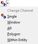
Change - Channel | Change the channel assignment for luminaires by single, window, all, within a polygon shape or within an entity (object/room). Single is the default mode of operation. |
|
|
Toggle luminaire templates on and off. If templates have not been enabled in this job file the first execution opens the Settings dialog. |
|
|
|
Set contour values, colors, line width and more . |
|
|
|
Delete all templates that have been defined. If templates are required at a later time, they will need to be recreated. |
|
|
|
Magnify the Model Mode symbol by a specified factor. This option is typically used in exterior lighting layouts to assist in viewing the luminaire locations. |
|
|
|
Create a luminaire group from individual luminaire locations. Luminaire groups may be oriented and arrayed. This is the default option. |
|
|
|
Explode a luminaire group into its individual locations. |
|

|
Aiming Vector (toggle) | Switch luminaire aiming vector visibility using a toggle behavior. Switch vectors on or off individually. |

|
Aiming Vector - Switch On | Switch luminaire aiming vector visibility On using single, window, all options. Default is single. |

|
Aiming Vector - Switch Off | Switch luminaire aiming vector visibility Off using single, window, all options. Default is single. |

|
Lock | Lock luminaires using single, window, all options. Default is single. |

|
Unlock | Unlock luminaires using single, window, all options. Default is single. |
|
|
Label the luminaires and specifies the labeling options. This is the default option. Labels may also be turned On and Off from this dialog. |
|
|
|
Delete individual luminaire labels. |
|
|
|
Move individual luminaire labels. |
|
|
|
Sort Luminaires by sequence numbers by selecting from several sorting schemes. |
|
|
|
Create an Aiming Diagram (used typically for Sports Lighting installations) for an existing luminaire location (or grouping). |
|
|
|
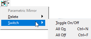
Add a parametric mirror. |
|
|
|
Delete a parametric mirror location. This is the default option. |
|
|
|
Break the parametric relationship between luminaires by switching a parametric mirror Off. |
Calculations Toolkit
|
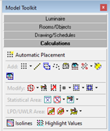
The Calculations Toolkit provides access to the commands to add and modify calculation points in your environment. Some buttons have multiple commands associated with them, which are available from the arrow to the right of the button. The secondary options are displayed below the correlated button. The default operation of a button click will be displayed in the menu with the icon adjacent to the command. |
|
Button |
Calculations Button Name |
Command |
|---|---|---|
|
|
Create calculation points on surfaces in rooms or on objects. Also includes a work plane option. |
|
|
|
Create a 2 Pt. grid of calculation points. This is the default option. |
|
|
|
Create a 3 Pt. grid of calculation points. |
|
|
|
Create lines of calculation points. |
|
|
|
Create a horizontal polygon of calculation points. |
|
|
|
Create scattered calculation points. |
|
|
|
Create a Daylight Factor calculation grid. |
|
|
|
Create a family of Glare Rating calculation grids. Each observer position generates a related grid. |
|

|
Create calculation grids specific to the computation of obtrusive light per AS-4282, CIE-150 and the MLO. Run compliance tests for each.
|
|
|
|
Create a calculation grid for roadway metrics (luminance, veiling luminance, etc.).
|
|
|
|
Create a family of Unified Glare Rating calculation grids. Each observer position generates a related grid or individual Observer value. |
|
|
|
Delete calculation points. The default option allows you to delete calculation grids individually. The secondary menu allows you to select Window. |
|
|
|
Edit calculation grids. |
|
|
|
Move calculation grids. |
|
|
|
Delete calculation grid labels. This is the default option. |
|
|
|
Move calculation grid labels. |
|
|
|
Remove calculation points. The default option allows you to remove calculation points within a polygon. The secondary menu allows you to select Single, Window or Within Entities. |
|
|
|
Replace removed calculation points. The default option allows you to replace calculation points within a window. The secondary menu allows you to select Window or All. |
|
|
|
Create a Statistical Area summarizing the calculation points included within. |
|
|
|
Delete the selected statistical area. |
|
|
|
Edit the properties of the selected statistical area. This is the default option. |
|
|
|
Move the label of the selected statistical area. |
|
|
|
|
Create an LPD and/or UWLR Area (Lighting Power Density and/or Upward Waste Light Ratio metrics). |
|
|
Delete an LPD or UWLR Area. Single selection is the default option |
|
|
|
Edit the properties of an LPD or UWLR Area. This is the default option. |
|
|
|
|
Move the label describing an LPD or UWLR Area to another location. |
|
|
Create Isolines in calculation grids. Turn Isolines On and Off. |
|
|
|
Highlight maximum, minimum and/or value ranges. Turn highlighting On and Off. |
Rooms/Objects Toolkit
|
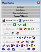
The Rooms/Objects Toolkit allows you to add and modify rooms in your environment. Some buttons have multiple commands associated with them, which are available from the arrow to the right of the button. The secondary options are displayed below the correlated button. The default operation of a button click will be displayed in the menu with the icon adjacent to the command. |
|
Button |
Room/Object Button Name |
Command |
|---|---|---|
|
|
Edit surface attributes for any selection of Rooms and/or Objects. The default version is Single selection (multiple select of any Object or Room type). The secondary menu provides additional selection options including Window and Window select by type (Object or Room). |
|
|
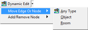
Dynamic editing of Room or Object nodes or sides. The default option moves a side when snapped to a center point, or moves a corner when snapped to a vertex. |
|
|
|
Create a room with a rectangular footprint and flat ceiling. This is the default option. |
|
|
|
Create a room with a rectangular footprint and barrel vault ceiling. |
|
|
|
Create a room with a rectangular footprint and gable ceiling. |
|
|
|
Create a room with a rectangular footprint and hip ceiling. |
|
|
|
Create a room with a rectangular footprint and pyramid ceiling. |
|
|
|
Create a room with a rectangular footprint and user defined ceiling. |
|
|
|
Create a room with a round/elliptical footprint and flat ceiling. This is the default option. |
|
|
|
Creates a room with a round/elliptical footprint and dome ceiling. |
|
|
|
Create a room with a round/elliptical footprint and user defined ceiling. |
|
|
|
Create a room with a polygon footprint and flat ceiling. |
|
|
|
Copy a room to other locations. |
|
|
|
Delete a room. |
|
|
|
Modify a room's properties (color, reflectance, height, etc.). |
|
|
|
Move a room to another location. |
|
|
|
Delete an individual room label. |
|
|
|
Move an individual room label. |
|
|
|
Create openings in Room wall surfaces. This is the default option. |
|
|
|
Create openings in flat (horizontal) Room ceiling surfaces. |
|
|
|
Create openings in Room floor surfaces |
|
|
|
Delete openings in Room surfaces. |
|
|
|
Create an Object with a rectangular footprint and flat top. This is the default option. |
|
|
|
Create an Object with a rectangular footprint and a Barrel Vault top. |
|
|
|
|
Create an object with a rectangular footprint and a Gable top. |
|
|
Create an object with a rectangular footprint and a Hip top. |
|
|
|
Create an object with a rectangular footprint and a Pyramid top. |
|
|
|
Object - Rectangular - Vertical Extrusion
|
Create an object with a rectangular footprint and user defined top. |
|
|
|
Create an object with a round/elliptical footprint and flat top. This is the default option. |
|
|
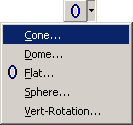
Create an object with a round/elliptical footprint and tapered top. The cone may taper up or down depending on a given positive or negative height. |
|
|
|
|
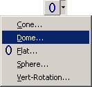
Create an object with a round/elliptical footprint and domed top. |
|
|
|
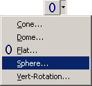
Create an object with a spherical (or round) shape. |
|
|
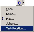
Create an object with a round/elliptical footprint and user defined top. |
|
|
|
|
Create an object with a user defined footprint and flat top. This is the default option. |
|
|
Create an object with a user defined profile and rectangular extrusion. |
|
|
|
Object - Planar |
Create a single-surface object. It has two dimensions only, no thickness. |
|
|
Insert a previously defined library object into the environment. Library objects are composite objects made of the above shapes that are stored independently and can be inserted into any file. They may be resized, and their surface characteristics (color, texture) may be changed. |
|
|
|
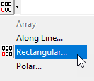
Array an object into a rectangular grid. |
|
|
|
Array an object into a circular or semicircular pattern. |
|
|
|
Copy an object to other locations. The default option is a single selection. Use the secondary menu to select Window. |
|
|
|
Create custom luminaire symbols used for calculation purposes and in AGi32's Render Mode. The default option is single selection (multiple objects may be individually selected at once). The secondary menu provides a Window selection option as an alternative. |
|
|
|
Delete an object. The default option is a single selection. Use the secondary menu to select Window. |
|
|
|
Disable objects to remove them from the calculations entirely. They are no longer visible.. |
|
|
|
Edit an individual object to modify its properties (color, label, wireframe color, height, etc.). Properties differ, depending on selected object type. To edit the surface properties of multiple objects and/or rooms, use the Surface Edit command instead. |
|
|
|
Explode a library object into its individual components. |
|
|
|
Move an object to another location. The default option is a single selection. Use the secondary menu to select Window. |
|
|
|
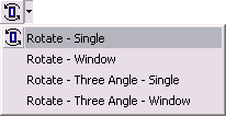
Rotate an object about a definable point in Plan, Isometric or Elevation view. The default option rotates a single object. The secondary menu provides a Window select option as an alternative. |
|
|
|
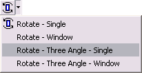
Rotate an object about a definable point in Plan or Isometric view using individual specifiable angles of rotation (Orient, Tilt and Roll). The default option rotates a single object. The secondary menu provides a Window select option as an alternative. |
|
|
|
Scale an object to uniformly increase or decrease its size. |
|
|
|
Delete an individual object label. This is the default option. |
|
|
|
Move an individual object label. |
|
|
|
Group individual objects into a reusable library object that is stored independently of the job file. Single select is the default option. Window selection is available from the secondary menu. |
|
|
|
Create openings in vertical side surfaces of Objects. This is the default option. |
|
|
|
Create openings in flat (horizontal) top surfaces of objects. |
|
|
|
Create openings in flat bottom surfaces of objects. |
|
|
|
Delets openings in objects.
|
|
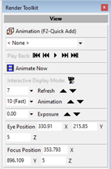
The View Toolkit in Render Mode provides controls for creating animated viewpoints in you rendered environment that can be exported as movies. |
|
Button |
Render View Button Name |
Command |
|---|---|---|
|
|
Create custom viewpoints to use in AGi32. To add the current Viewpoint to the list, use the F2 keyboard button. |
|
|
|
|
Indicates current scene and allows user to select alternate scene if defined. Scenes are definable in Viewpoints dialog. |
|
|
Render-Viewpoint Slideshow |
Scroll through the defined viewpoints. |
|
|
Animate the Viewpoints in the current scene using the Viewpoint parameters specified in the Viewpoints dialog. |
|
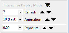
|
Toggle the button to switch between slow and fast refresh and animation speeds. Alternatively, the values in the Refresh, Animation, and Exposure cells may be adjusted by selecting a new value from the drop-down list, or the up/down arrows may be used to adjust incrementally. |
|
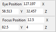
|
The View Parameters from the View Properties command are also exposed for convenience in the Render Toolkit. |
Reports Drawing/Schedules Toolkit
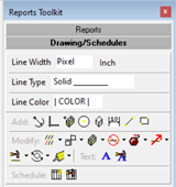
|
The Drawing/Schedules Toolkit allows you to add and modify drawing entities (lines, circles, text) and schedules in your the Reports environment. Some buttons have multiple commands associated with them, which are available from the arrow to the right of the button. The secondary options are displayed below the correlated button. |
|
Button |
Reports Drawing/Schedules Button Name |
Command |
|---|---|---|
|
|
Modify the current drawing entity line width. The default line width is 1 Pixel. |
|
|
|
Modify the current drawing entity line type. |
|
|
|
Line Color |
Modify the current drawing entity line color. |
|
|
Creates an arc. |
|
|
|
Creates an axis in the X, Y or Z direction. |
|
|
|
Inserts a previously defined block. |
|
|
|
Creates a circle. |
|
|
|
Creates a cube. |
|
|
|
Creates a dimension line in the X, Y or Z plane. |
|
|
|
Creates a line. |
|
|
|
Creates a rectangle. |
|
|
|
Copy drawing entities into a rectangular grid. The default option is a single selection. Use the secondary menu to select Window or All. |
|
|
|
Copy drawing entities to other locations. The default option is a single selection. Use the secondary menu to select Window or All. |
|
|
|
Creates a global block from the selected entities. The block is accessible from any job file. The default option is a single selection. Use the secondary menu to select Window or All. |
|
|
|
Deletes the selected drawing entities, including schedules. The default option is a single selection. Use the secondary menu to select Window or All. |
|
|
|
Explodes a block or text entity into individual components (drawing entities or text lines). The default option is a single selection. Use the secondary menu to select Window or All. |
|
|
|
Move drawing entities (including schedules) to another location. The default option is a single selection. Use the secondary menu to select Window or All. |
|
|
|
Change the color and/or line type of the selected drawing entities. Does not operate on Schedules. The default option is a single selection. Use the secondary menu to select Window or All. |
|
|
|
Rotate the selected entities. The default option is a single selection. Use the secondary menu to select Window or All. |
|
|
|
Scale the selected entities. The default option is a single selection. Use the secondary menu to select Window or All. |
|
|
|
Create text or insert text files into your job file. |
|
|
|
Modify the properties of the selected text. |
|
|
|
Create a dynamic schedule that extracts information about your job file. |
|
|
|
Modify the properties of the selected schedule. |
Reports Toolkit
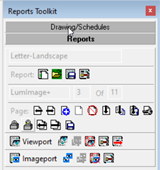
|
The Reports Toolkit provides tools that assist in creating custom output in AGi32. |
|
Button |
Button Name |
Command |
|---|---|---|
|
|
Create a new Report |
|
|
|
Load an existing Report |
|
|
|
|
Save the current report as a template to use with other job files. |
|
|
Change the current reports properties (page sizes, protection, page names, etc.) |
|
|
|
Current Page |
Display the current page number and total page count. |
|
|
Display Previous Page |
Display the previous page in the report. |
|
|
Display Next Page |
Display the next page in the report. |
|
|
Set the current page as the Master design template for easy specification of repeating elements across the report. |
|
|
|
Clear All Entities From Current Page |
Clear the current page of all entities. |
|
|
Delete Current Page |
Delete the current page and all its elements. |
|
|
Insert Blank Page |
Insert a blank page after the current page. |
|
|
Insert Copy Of Current Page |
Insert a copy of the current page after the current page. |
|
|
Insert Saved Page |
Insert a previously saved page after the current page. |
|
|
Lock/Unlock Page |
Toggle the Lock/Unlock status of the current page. Locking a page prevents it from being modified. |
|
|
Move Current Page Left |
Move the current page to the left. |
|
|
Move Current Page Right |
Move the current page to the right. |
|
|
Save Current Page |
Save the current page for use with other job files. |
|
|
Create a dynamic Viewport that links to a View specified in Model Mode. |
|
|
|
Copy an existing Viewport. |
|
|
|
Paste a Viewport you have just copied. |
|
|
|
Delete a Viewport. |
|
|
|
Opens the Viewport Properties dialog. |
|
|
|
Move a Viewport. |
|
|
|
Create a static Imageport that contains a rendering, Instabase image, or graphic image. |
|
|
|
Copy an existing Imageport to the clipboard. |
|
|
|
Paste an Imageport that has been copied using the Copy Imageport command. |
|
|
|
Delete an existing Imageport. |
|
|
|
Access the Properties of the Imageport where you can change image and control its attributes. |
Statistics Window
 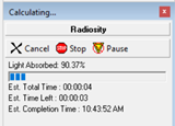 |
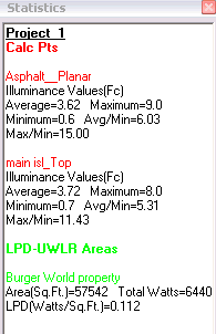
The Statistics Window displays the summaries of calculated metrics as well as Calculate options during the Calculation process. |
|
Button |
Calculate Options Button Name |
Command |
|---|---|---|
|
|
|
The Statistics Window title bar indicates the current function. When the environment is being calculated, the Title Bar text changes accordingly. |
|
|
|
While the environment is calculating, the current process is displayed. Processes include: Radiosity, Calc Points |
|
|
Cancel the calculations without completing. No calculation points results will be displayed. |
|
|
|
Stop the calculation process at the current stage. If the radiosity process is stopped prematurely, calculation points will be computed from the current light levels. |
|
|
|
Pause the calculations to interact with the environment, then resume calculations. Note, the calculation process need not be paused to interact with the environment in Render Mode (you can navigate and change the display properties while calculating); however pausing the calculations may be desirable to free up some CPU resources if needed at a given time. Calculations may be paused in Model Mode or Render Mode. Note: Minimizing AGi32 while calculating will allocate to the calculation processes a lower priority amongst other processes. |
|
|
|
The Light Absorbed value indicates how much of the progressive radiosity solution has been completed. The progress bar indicates the percentage completed (graphical indication). The estimates for Total Time used when completed, Time Left, and Time of Completion are shown as well. |
|
|
|
Displays the summary information for calculation entities such as point-by-point grids, LPD/UWLR Areas and Statistical Areas. |
Global Modify Commands Panel
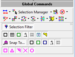
This panel provides centralized access to frequently used modification commands across all entity types. It includes:
- Move
- Rotate
- Copy
- Scale
- Mirror
- Rectangular Array
The panel appears docked on the right by default and can be repositioned. Users can filter commands by applicable entities (e.g., Objects, Rooms), improving precision during multi-entity edits.
Restoring Toolkits
To restore the default factory Toolkit positions, on the main menu bar, click on the Tools - Restore Default Toolkits command.


