The Roadway Optimizer tool provides you with a means of designing typical straight roadway sections using illuminance and/or luminance criteria. You may optimize the pole locations based on known illuminance and/or luminance criteria, or calculate the metrics for given pole spacings. The luminance criteria may be calculated in accordance with IES, CIE, BSEN, Australia, or New Zealand methods. Up to five layouts may be created and compared at any one time.
Objects are not considered in the Roadway Optimizer's estimated calculations.
The Roadway Optimizer tool and Roadway Calculations command provide assistance in computing calculations for straight segments of roadways using IES, CIE, BSEN, Brazilian, CIE-Australia, or CIE-New Zealand methods. You may select from several R-Tables, which provide information to the software on the nature of the light reflected from various pavement types. You may specify the width of the road, the number of lanes, the existence of a median and its width, whether the luminaires are in mounted in an opposite or staggered configuration, and whether they are at the edge of the road, have a setback or are median mounted.
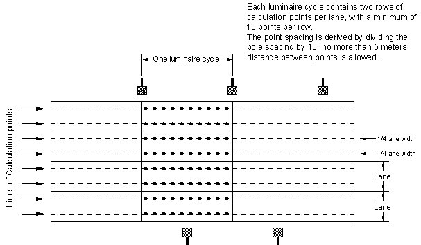
A description of the design criteria and some recommended values are provided in the Calculation Metrics topic. A diagram of the ANSI-IES RP-8-18 Roadway grid layout is given here.
ANSI-IES RP-8-18 RoadwayLayout

Roadway Optimizer Results
When the calculations are complete, you will be presented with the statistics for the standard that you selected. For example, if IES RP-8 is selected, the statistics will include illuminance, luminance, veiling luminance, and Visibility Level (STV) calculated results. (For RP-8, Background Luminance and Target Luminance are also calculated, for Visibility Level.) Luminance on the pavement is based on the quantity and direction of light, observer location, and the pavement reflectance characteristics. Illuminance simply informs us of the amount of light incident on the pavement without regard to the pavement's surface type or angle of observation.
The order of the Optimization Criteria may be changed. Calculating based on a different criteria order may produce different results for luminaire spacing.
Once the calculations are completed and the requested criteria met, you may print out the results. You may also Export the layout into AGi32’s Model Mode to incorporate it into your design.
An anomaly may occur when Average Luminance is given top priority. If the optimization process begins with an initial pole spacing that is greater than 12 times the mounting height, the luminance results will be "off the chart" in the sense that the R-Tables do not contain data past 12 mounting heights' distance. When this happens, Roadway Optimizer may not be able to properly carry out the optimization process. The result in such a case is luminaire spacing that is not optimal. There are two ways to avoid this.
- In Settings (within Roadway Optimizer), change the Maximum Allowable Spacing to 12 x MH. (Default is 30.)
- Change the order of the optimization criteria so that Average Luminance is not given highest priority.
Compatibility with earlier versions: Optimization order is set (cannot be modified) in version 2.17 and earlier. Therefore, if the order is different in version 2.2 or later, you may get different results (spacing) when recalculated in an earlier version.