Add Calculations - Illuminance along Lines
This command allows you to create lines of points for which illuminance values will be calculated. Lines are specified in Plan view. Different Z coordinates may be entered for each vertex allowing you to create lines of varying elevations (great for interchanges). Multiple parallel lines may be included in each definition by using the Array option.
- From the Add
menu choose Calculations - Line,
or from the Calculations Toolkit select
 .
. - Specify a unique label up to 32 characters. The default label will be CalcPts_1. Unless changed, subsequent labels will be CalcPts_2, CalcPts_3, etc. If a number is used for the label, subsequent labels will be incremented accordingly.
- An optional description may be entered up to 80 characters. Meaningful descriptions that include spacing and elevation information will be useful when generating schedules.
- Specify the point spacing. By default, a point spacing of 10 is used. As the point spacing changes, the text size adjusts, automatically.
- Selecting the option to Center Points Relative To Each Line Segment will prevent points from landing on the ends or at vertices of the line. If the segment length is less than the point spacing, one point will be placed in the center of the line segment. If this option is not selected, the first point will be a the beginning of the first segment of the line, and the remainder of the points will be spaced without regard to vertices in a multi-segment line.
- Select the light meter type.
- Specify the Summary options to calculate. By default, average, maximum and minimum illuminance are displayed along with uniformity ratios (Max/Avg ratio is not selected by default). If Number of Points is selected, the number of points that are in the calculation (not including points that have been removed) is shown.
- Select the display options, including decimals to display, text and line color, visible lines, point markers, meter direction indicators, and labeling.
- Select the method for creating the line: specify manually or by selecting an existing Drawing entity.
- If desired, an Array of lines may be created. The array may be horizontal, on one or both sides of the original drawn or selected line, or it may be vertical above the original line. The Number of Array Lines does not include the original line. The Total Number of Lines does include the original line. Calculation points are placed on all of the lines.
- If desired, specify Highlight Values by clicking on the appropriate button.
- Click OK.
- If you chose to Select Existing Drawing Entity for the line, place the pickbox over the line and left click. The line selected will be displayed bold. You may press Enter or right click to accept it, or Esc to cancel the operation, or Undo (Ctrl-Z) to reselect the line.
- If manually drawing the line, you may change the line elevation by moving the cursor
into the Z-Coord text box and enter a new value or use the up and down
arrow keys on the keyboard, before clicking the first point. Locate the
first point of the line and click the left mouse button.
- Drag the cursor to the second vertex on the line and left click again. By default, the Z coordinate will echo the first vertex's elevation. To change the elevation for the vertex, before clicking move the cursor into the Z-Coord textbox and enter a new value or use the up and down arrow keys on the keyboard.
- Continue in this fashion until the line is complete. Right click the mouse to end the line at the last vertex.
- If you selected Along Line or Perpendicular to Line for the meter direction, AGi32 will show you the tentative direction that the meter is facing. You may press the F5 button on your keyboard to flip the direction. Press the Enter button or right click to accept the meter direction shown.
- If you selected to array the calculation lines horizontally on one side of the original line, AGi32 will show you the tentative direction that the array will be created. You may hit the F5 button on your keyboard to flip the direction and create the array on the other side of the original line. Press the Enter button or right click to accept the array direction shown.
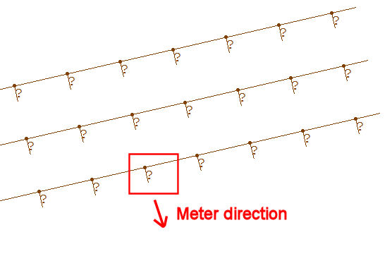
The line(s) of points will be created as specified. The direction of the meter will be indicated as a small vector line attached to each calculation point. The meter indicators are "on" by default. They may be turned off by unchecking the appropriate box in the dialog. In this example of an Array of three lines of points, the Meter is vertical and its direction is Perpendicular to the line: