AGi32 provides up to four light meter types when specifying illuminance calculation entities:
|
Calculation Type |
Available Light Meters |
|---|---|
|
Grid |
Horizontal, Normal to Grid, Fixed, Variable |
|
Line |
Horizontal, Vertical, Fixed, Variable |
|
Polygon |
Horizontal, Fixed, Variable |
|
Scattered |
Horizontal, Fixed, Variable |
Horizontal - The light meter at each point measures horizontal illuminance. There is no need to specify the calculation entity's vertices (or corners) in any particular order.
Vertical - The light meter at each point measures vertical illuminance, light falling onto a vertical plane. There is no need to specify the calculation entity's vertices (or corners) in any particular order.
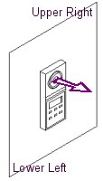
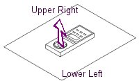
Normal to Grid - The light meter at each point will be located parallel to the grid's active surface and will measure light falling onto the grid's active surface. The grid is specified by locating the lower-left-hand corner and the upper-right-hand corner of the active surface. The direction of the light meter is displayed as the cursor is moved away from the first point. You may flip the grid’s active side if desired, before clicking the second point, by pressing the F5 key on the keyboard.
|
· If the meter faces up or toward you, locate the 1st point of the grid at the lower-left corner of the grid and the 2nd point at the upper-right corner of the grid. · If the meter faces down (e.g., a ceiling plane) or away from you, locate the 1st point of the grid at the upper-left corner of the grid and the 2nd point at the lower-right corner of the grid. |
|
|
|
Fixed - The light meter at each point is specified with fixed orientation and tilt angles independent of the calculation entity's orientation or slope. The meter's default position, before any Orientation or Tilt angles are applied, is facing up, and east = 0 degrees.
|
|
The orientation angle is measured counterclockwise from due east. Before applying a Tilt, rotate (orient) your meter counterclockwise from east to 180 degrees opposite the direction that you want it to face! For example, if you want the meter to face north when titled, it needs to be rotated (orientated) 270 degrees. |
|
|
A positive tilt angle rotates the 0-degree plane (front of meter) up, toward zenith, and the face of the meter "leans" backward. For example, with Orient=0 (the front of the meter faces east), a Tilt of 45 degrees tilts the meter so that it is still pointed somewhat upward but slightly "backward," toward west. Another example: Beginning with an Orient angle of 90 degrees (front of meter faces north), a Tilt of 90 degrees tilts the meter all the way back so that it is pointed at the south horizon. |
When the calculation entity is created, its vertices (or corners) may be specified in any order. This method is often used to specify vertical illuminance on a horizontal plane. It can also be used to specify illuminance at an angle other than strictly horizontal or vertical.
The following table contains the Orient and Tilt angles to use for four common meter aimings:
|
Meter Aiming |
Orient Angle |
Tilt Angle |
|---|---|---|
|
Vertical meter facing West (toward -X) |
0 |
90 |
|
Vertical meter facing South (toward -Y) |
90 |
90 |
|
Vertical meter facing East (toward +X) |
180 |
90 |
|
Vertical meter facing North (toward +Y) |
270 |
90 |
Variable
|
|
The light meter at each point is aimed toward a specific point. Each calculation point has a different Orient (and possibly Tilt) angle, depending on its location relative to the specified aiming point. This is most commonly used for television lighting where the specified point indicates a camera location. Specify the point by entering its X, Y and Z coordinates in the appropriate cells, or click on the Specify button to locate the point in the graphics window. |