Create Custom Luminaire Symbol
Custom luminaire symbols can make your visualizations more realistic or your line drawings in Model mode more suitable to your clients. It's easy to create a custom symbol for only Model mode (Drawing symbols) or for both Model and Render modes (Calculation symbol). Here are some basic rules and caveats.
Before you begin, plan your design. If you want to create a symbol that can be used in both Model and Render modes you will create it using the AGi32 Object tools exclusively (or import 3D entities, see below). In this way there will be a line drawing automatically generated when the Create Symbol command is run. Conversely, if you would like to create a simple line drawing symbol to be used in Model Mode only, you can do this using the AGi32 drawing tools or by using imported 2D line information from DWG/DXF.
Creating a Calculation symbol for both Model and Render modes:
- Create the symbol using AGI32’s objects commands, or import a 3D CAD file into AGi32 (choose to import the 3D entities as objects).
- Using Surface Edit, in the Advanced Surface Properties section, designate at least one surface of the object as luminous by setting the Luminance (cd/sq.m) to a value greater than zero. Note that the Luminance value itself is irrelevant; any positive value is an indicator (e.g., you can assign a Luminance value of 1 for simplicity). If importing, use the Import Mapping feature to set the luminous surfaces rather than doing it in Surface Edit.
- Go to the Modify menu and select Object - Create Luminaire Symbol, or from the Rooms/Objects toolkit select
- Select the objects used to create the symbol. Default selection option is Single. Single allows you select multiple objects one at a time (right-click to complete command). Window and All selection options are available from the pull-down menu.
- Specify the point on the symbol that will correspond to the luminaire insertion point, this is typically the center of the luminaire. The Z coordinate of the insertion point should be 0.
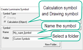
- In the dialog you can name the symbol and select a folder to store it. New folders will be created inside the LuminaireSymbols folder (C:\ProgramData\AGi32\LuminaireSymbols).
- Click OK, the symbol is ready to use.


Importing 3D content
You can import DWG or LAIDEX (from Sketchup) formats and make them into luminaire symbols. However, a strong note of caution here: symbols constructed from complicated 3D content may be too surface heavy to be useful in AGi32. To be successful your symbols should be less than 500 surfaces (much less). The fewer surfaces the easier the symbol will be to use and the less memory it will consume. Be sure to use the Import Mapping feature in AGi32 to set your luminous surfaces (luminance=1) during the import process rather than trying to find those surfaces in the Surface Edit command after importing.
Calculation Symbol Rules
- Keep in mind, exterior symbols seldom appear detailed in Render mode due to the dark nature of the environment, unless they are being illuminated from a light source above their elevation. Don't waste calculation time on complicated symbols you will never be able to recognize!
- Symbols in Render Mode are created using objects in AGi32. The current object properties (surface color, reflectance and wireframe color) are not maintained when creating a symbol. The user can specify these properties when selecting the symbol in the Luminaire Define dialog. The housing of the symbol (surfaces with reflectances > 0) are assigned one global housing color (50% gray). The exception to this are surfaces with non zero Luminance values. These surfaces define the luminous surfaces of the luminaire.
- Imported 3D CAD models converted to objects may also be used, as long as Luminance is assigned to the luminous surfaces (See rule #4).
- Surfaces with non-zero reflectance and zero luminance are assigned as housing surfaces. Surfaces with positive luminance values are assigned as the luminous surfaces of the symbol. You can assign a luminance value using the Surface Edit command, or using the Import Mapping feature when importing 3D content. The Luminance value itself is irrelevant - any positive value is an indicator (e.g., you can assign a Luminance value of 1 for simplicity).
- Surfaces may be removed to simplify the symbol or to create more-complex symbols.
- Openings are NOT supported . Instead of openings, you can break the surface into segments to fashion the opening
- Transmittance values are not considered in the symbol creation.
- All surfaces in the symbol also become single sided, regardless of their original surface type. The original surface normal direction applies, and may need to flipped before the symbol is created, using the Surface Edit command. Normals should point outward.
- Any object may be edited to change one of its surface attributes. For example, to create a 2x4 lensed troffer symbol, you could create a 2x4 Rectangular-Flat object. Edit the object and assign a Luminance value of 1 cd/m2 to the bottom surface to assign it as the luminous surface.
- As a general rule, symbols should be created at Z=0 and above or at Z=0 and below. A symbol can have surfaces above and below 0, if it is best to be inserted at it's center point. Symbols that are located at Z=0 and above are assigned an insertion point = Bottom for the symbol. Symbols that are located at Z=0 and below are assigned an insertion point = Top for the symbol. Surfaces above and below Z=0 will trigger an Insertion Point = Center. The insertion point for the luminaire should also be placed at Z=0 when creating the symbol.
- When creating symbols with yokes, the distance between the luminous surface and the yoke base should be at least 1 foot. This distance separates the luminous box from the pole enough so that the pole does not obstruct the luminous box. We recommend creating the base of the yoke at Z=0 and the remainder of the symbol above to insert the symbol at the bottom of the yoke.
- When creating ceiling-recessed symbols, create the symbol housing at Z=0. Create the luminous surface slightly below the symbol at Z = -0.01 or less. The symbol will be inserted at the Top of the symbol.
Creating a Drawing symbol for Model mode only:
- Create the symbol using AGI32’s drawing commands, or import a 2D CAD file into AGi32 (line drawings).
- Go to the Modify
menu and select Drawing Entity - Create Luminaire
Symbol, or from the Drawing Entities toolkit select
 .
. - Select the lines used to create the symbol. Default selection option is Single. Single allows you select multiple objects one at a time (right-click to complete command). Window and All selection options are available from the pull-down menu.
- Specify the point on the symbol that will correspond to the luminaire insertion point, this is typically the center of the luminaire. The Z coordinate of the insertion point should be 0.
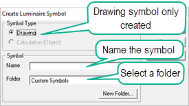
- In the dialog shown below you can name the symbol and select a folder to store it. New folders will be created inside the LuminaireSymbols folder (C:\ProgramData\AGi32\LuminaireSymbols).
- Click OK, the symbol is ready to use.

