
![]()
Arraying Luminaires - Concepts
Arraying luminaires provides a variation of the Copy Luminaire command, where a fixed replication pattern is specified for each subsequent luminaire location.
Luminaires may be arrayed along an existing line or one that is drawn. The following parameters may be set in the dialog:
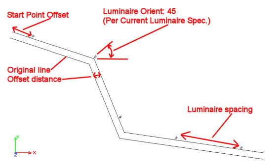
Orientation: Luminaire orientation may be along the line, perpendicular to the line, or according to the specification in the Luminaire Toolkit.
Mounting Height: The mounting height may be that specified in the Luminaire Toolkit, or it may be with respect to the Z-Coordinate of the line drawn or selected.
Array: The array may be created based on a Set Spacing or on a Set Quantity of luminaires to fall within the array boundaries. Selecting Start Point Offset allows the first luminaire in the array to be offset from the endpoint of the array.
Luminaire Line: The line may be Manually Specified or the user may Select an Existing Drawing Line. If the line is manually drawn, you may choose to Add The Line As a Drawing Entity. Note: Once placed, the luminaires are no longer associated with the line. If they are moved or deleted, the line remains. The line of luminaires may also be offset from the drawn or selected line. This might be useful for placing roadway luminaires at a specific distance from a curb line. Again, the offset line may be added as a drawing entity if desired.
Note: Sometimes AGi32 will not be able to create an array from lines composed of multiple segments, depending on the geometry of the line itself and the details of the array specification. In this kind of situation, AGi32 will provide a pop-up Hint to explain that it cannot be done.
Rectangular arrays specify subsequent luminaire locations in a 2D or 3D rectilinear pattern using dynamic spacings between a given number of luminaires, or dynamic luminaire placement for constant spacing parameters. Use luminaire arrays whenever you need to create a linear or rectangular grid of luminaires. Arrays can be diagonal by simply specifying the left and right vertices at the desired angle.
The array Quantity always includes the first luminaire. The array also includes at least one luminaire in all three dimensions- since each luminaire exists in all three dimensions. Quantity and Spacing are always entered as positive values.
Rectangular Array - 1 Direction
Rectangular Array: Set Spacing 10 Left to Right; 0 Top to Bottom; Initial luminaire location indicated in Red
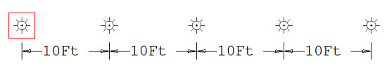
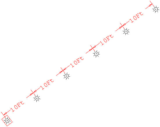
Rectangular Array: Set Spacing 10 Left to Right; 0 Top to Bottom; Initial luminaire location indicated in Red - Left to Right only indicates relative direction of 1st two vertices, there is no requirement to create an orthogonal array (parallel to the Cartesian coordinate axis)
Rectangular Array - 2 Directions
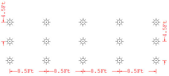
Rectangular Array:
Set Quantity:
5 Left to Right; 3 Top to Bottom;
Luminaire Offset: Fixed Distance: 3 LR and 3 TB
Resultant spacing based on vertices input and offset distance
Rectangular Array:
Set Spacing:
10 Left to Right; 0 Top to Bottom; Z-Direction - Quantity 3; Z Spacing
20
Resultant Left to Right quantity based on vertices input
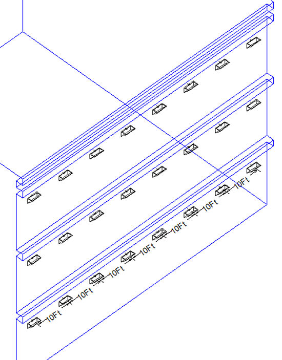
Rectangular Array - 3 Directions
Rectangular Array:
Set Spacing:
4 Left to Right; 70 Top to Bottom; Z-Direction - Quantity 2; Z Spacing
2
Resultant Left to Right and Top to Bottom quantity based on vertices input
Rectangular Luminaire Arrays - Procedure
Polar arrays specify a luminaire pattern in a circular or semi-circular manner. Polar arrays work very well in circular spaces, such as rotundas and domes, when you need to create an evenly spaced circular pattern. Inputs include the selected luminaire, array center (center of proposed circle or semicircle), number of luminaires, and luminaire rotation. Unlike rectangular arrays, which leave the luminaire aiming unchanged, you may choose to orient the luminaire toward, away from, or perpendicular to the center of the array circle.
Polar arrays create a perfectly circular or semicircular pattern. You may move luminaires apart from one another (for example to fit within an ellipsoidal shape) once the array is finished.
The angle between the selected luminaire (the first in the array) and the polar center indicates the starting angle of the polar array. To create a complete circle, enter this angle as the Ending Angle as well.
Luminaires can be duplicated along a circular or semi-circular path using the Modify-Luminaire-Polar Array command. The specification criteria includes Starting and Ending angles of the Array, center point, number of locations to be produced and luminaire orientation. The luminaire orientation can either be the same as the original, directed inward or outward from the array center, or perpendicular to the array center.
Selection Point - When the Luminaire -Polar Array command is initiated, the cursor changes to a pickbox so that an individual luminaire, luminaire arrangement or luminaire group may be selected. The selection point always moves to the insertion point of the luminaire, regardless of the actual selection point.
Array Center Point - Once the luminaire is selected, you are prompted for the location of the polar array center. The distance specified is the radius of the array and dictates the distance that each duplicate luminaire will be located from the array center. The angle between the selection point and the array center is the Starting Angle. This starting Angle may not be altered, so choose your center point deliberately. Tip: Polar Arrays are always created in a counter clockwise direction.
Careful selection of the array center point will allow you to create symmetrical arrays or relatively abstract ones.
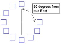
Starting Angle - The Starting Angle of the array is determined by the angle formed between a line formed from selection point to array center and a line formed between array center to due East. This angle cannot be entered manually by the user; it is determined by the location of the selection point and the array center point.
|
|
|
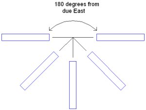
Ending Angle - The Ending Angle of the array dictates the location of the last luminaire to be placed in the array. If the Ending Angle is equal to the Starting Angle the array will form a complete circle. In this case, there will be a luminaire placed at the Starting Angle but not the Ending Angle, otherwise two luminaires would occupy the same position. If the Ending Angle does not equal the Starting Angle, a luminaire is placed at both the Starting and Ending Angles.
Number of Locations - This value indicates the total number of luminaires in the polar array, including the original luminaire. The total number of luminaires in the array must be two or more.
Angle Increment - This value describes the angle between each pair of luminaires in the polar array.
- If Starting Angle Does Not Equal Ending Angle - Angle Increment is calculated this way: (Ending Angle - Starting Angle) / (Number of Locations - 1)
- If Starting Angle Equals Ending Angle - Angle Increment is calculated this way: (Ending Angle - Starting Angle) / (Number of Locations)
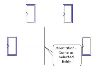
Entity Orientation - Four selections are provided for luminaire orientation.
- Same as Selected Entity - Indicates that all luminaires created in the array will be oriented the same as the original.
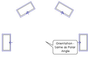
- Same as Polar Angle (Orient away from center of array) - Indicates that all luminaires created in the array will be oriented away from the array center and in alignment with the displacement vector.
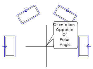
- The Opposite of Polar Angle (Orient towards center of array) - Indicates that all luminaires created in the array will be oriented towards the array center and in alignment with the displacement vector.
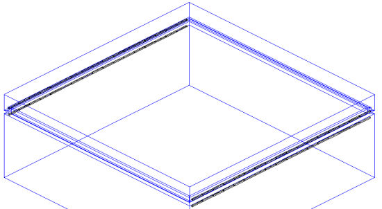
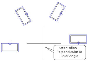
- Perpendicular to Polar Angle (Orient perpendicular to center of array)-Indicates that all luminaires created in the array will be oriented perpendicular to center of array and the displacement vector. This option is best for linear luminaires placed in a round or circular position, such as a cove.
|
Orientation - Same as Selected Entity |
Orientation - Same as Polar Angle (Orient away from center of array) |
|
Orientation - Opposite Of Polar Angle (Orient towards center of array) |
Orientation - Perpendicular To Polar Angle (Orient perpendicular to center of array) |
Polar Luminaire Arrays - Procedure