
The Luminaire-Rectangular Array command allows you to create a uniform line or grid of luminaires in any direction using Dynamic or Static luminaire placement. The rectangular array is comprised of replicated luminaires or luminaire groups in the X, Y and Z directions.
- From the Modify
menu choose Luminaire-Rectangular Array,
or from the Luminaire toolbar select

- The Rectangular Luminaire Array dialog appears with tow tabs: Dynamic Array Placement and Static Array. The tab shown by default at the forefront is the Dynamic Array Placement.
 Dynamic
Luminaire Placement: This tab allows the user to initialize the array
by using an existing luminaire location or the current luminaire specification.
Dynamic
Luminaire Placement: This tab allows the user to initialize the array
by using an existing luminaire location or the current luminaire specification.
- Select From Existing Location - This option allows the user to select an existing luminaire as the 1st luminaire in the array. The attributes (Label, MH, Aiming Parameters - Orient, Tilt, Roll and Spin) of the selected luminaire will be used for all subsequent luminaires in the array.
Note: You must Define and Locate a luminaire to use this option
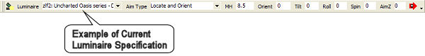
- Use Current Luminaire Specification (New Location)
- This option allows the user to use the attributes (Label, MH, Aiming
Parameters - Orient, Tilt, Roll and Spin) of the current luminaire specification
on the Lum Define toolbar for all luminaires in the array.
In this method, users may choose to Orient the luminaire relative to the array boundary direction, in lieu of using the current specified Orient angle. The following three Luminaire Orientation options are available:
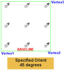
- Use Specified Orient – All luminaires in the array will use the current Orient specified in the Luminaire Define toolbar.
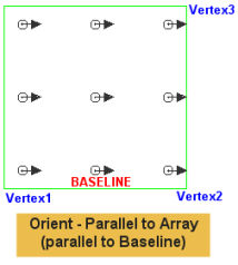
- Parallel to Array (Along Left-Right) – All luminaires in the array will be oriented parallel to the array baseline (along the left-right boundary - equivalent to the 1st and 2nd vertices of the array).
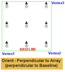
- Perpendicular to Array (Along Top-Bottom) – All luminaires in the array will be orientated perpendicular to the array baseline (along the top-bottom boundary of the array – equivalent to the 2nd and 3rd vertices of the array).
Specified Orient
Parallel to Array
Perpendicular to Array
Note: You must specify the current luminaire parameters before selecting the Array Luminaire command, attempting to specify the luminaire parameters after specify the array will cancel the command.
- The Array Specification section prompts you to specify the Array Type and Offset from the boundaries (if any).
- Select the Array Type - Set Spacing or Set Quantity:
- Set Spacing - This option allows you to set a fixed spacing for the Left-Right and Top-Bottom boundaries of the array. Either spacing may be set equal to zero to create a one dimensional array (line) of luminaires. The Quantity specified in each direction will be dynamically displayed based on the specified boundaries and Offset parameters. Note: If the Top-Bottom Spacing = 0, AGi32 will only prompt you for vertices 1 and 2. If the Left-Right Spacing = 0, AGi32 will prompt you for all three vertices.
- Set Quantity - This option allows you to set a fixed quantity for the Left-Right and Top-Bottom boundaries of the array. Either Quantity may be set equal to one to create a one dimensional array (line) of luminaires. The Spacing specified in each direction will be dynamically displayed based on the specified boundaries and Offset parameters. Note: The Array Quantity always includes the 1st luminaire in the total count.
- To add additional luminaires in the Z direction and create a three dimensional luminaire array, specify the Quantity and Spacing for the Z boundary. By default, only a single luminaire is created in each Z location making for a two dimensional array.
- Specify the Luminaire Offset. Not all options are available for all Array selections:
Offset Option
Existing Location
Current Specification
Set Spacing
Set Quantity
No Offset
Yes
Yes
Yes
Yes
Fixed Distance
Not Available
Yes
Yes
Yes
Center - Relative to Array Boundaries
Not Available
Only For Set Spacing
Yes
Not Available
- No Offset: - Luminaires are not offset relative to the first luminaire in the array or the array boundaries
- Fixed Distance - Luminaires are offset left-right and top-bottom relative to the array boundaries. Offsets must be >=0
- Center Luminaires - Luminaires are centered left-right or top-bottom or in both directions relative the array boundaries:
- Centered left-right only – Luminaires are only centered left-to relative to the array boundaries. As a result, luminaires may end up on the array boundary lines (top and bottom) depending on the spacing and distance top-bottom.
- Centered top-bottom only - Luminaires are only centered top-to-bottom relative to the boundaries. As a result, luminaires may end up on the array boundary lines (left and right) depending on the spacing and distance left-right.
- Centered in both directions – Luminaires are centered in both directions. No luminaires will be located on the array boundaries.
Set Spacing: 5 Left to Right; 5 Top to Bottom 
Set Quantity: 3 Left to Right; 3 Top to Bottom
- Click Ok.
- If Select From Existing Location was chosen, select the 1st luminaire in the array. Otherwise, click the first vertex of the array boundary. Hint: If no Offset was specified, this is the location of the 1st luminaire in the array.
- Click the second vertex of the array boundary.
- Click the third vertex of the array boundary (not necessary if Top-Bottom Spacing = 0 in Set Spacing section).
- Static
Array: This tab allows the user to apply rectilinear array settings to
an existing luminaire location.
- Enter the quantity and spacing in each primary X, Y and/or Z direction. The total quantity must include the original luminaire in each set. For example if you wish to create three additional luminaire locations, spaced 10 feet apart in the X direction, the array quantity would equal four.
- Each luminaire in the array is a replica of the selected existing location (aiming parameters, MH, etc.)
- Negative values may be entered for spacing values. Quantity values must be positive.
- By default, the luminaire positions in array are created orthogonally, parallel to the X and Y axis. To rotate the entire array at some angle offset from the X axis (due East equaling zero), entire the array angle in theArray Angle text box.
- Click Ok.
- Select the luminaire to use as the starting point for the array.