
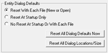
System Settings is used to set your preferences for software operations. You may elect to permanently change some startup settings for all future sessions with the software. To do so select the Save Settings As Startup Defaults checkbox after making the change in the dialog. If this is not selected, any modifications will only apply to the current job file. When the job file is saved, certain system settings will automatically be saved along with the drawing contents. Using the Reset Defaults button you can elect to reset defaults from a specific tab or All tabs.
- From the main menu, select Tools - System Settings, or from the Common toolbar, click on the System Settings
button
 .
.
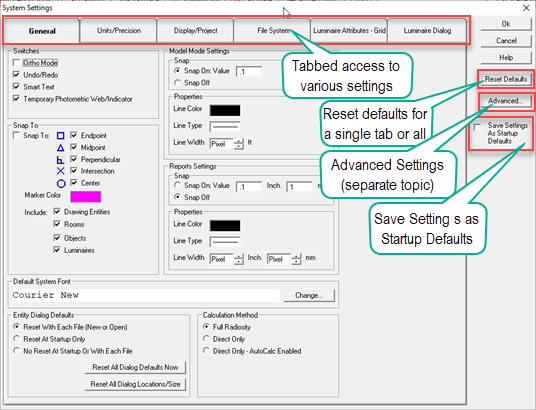
The System Settings dialog also provides access to the Advanced Settings dialog. Please use caution when modifying the settings in the Advanced Settings dialog, as you may hinder the productivity of this software inadvertently. We recommend that these settings remain unchanged unless you are specifically instructed to modify them by Lighting Analysts .
Note: Please see System Parameters for a listing of system parameters and default settings.
General Tab

Units/Precision Tab
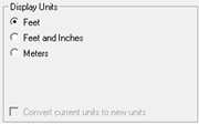
The Units tab specifies the settings for distance and illuminance units as well as some lighting metric parameters. The default number of decimal places used to display calculation values and the point demarcation is specified here, as well. Modifying the Display and Illuminance Units will change the current job file and possibly necessitate recalculation.
|
Setting |
Default Value / Included in Job File (Y or N) |
Description |
||
|---|---|---|---|---|
|
||||
|
Feet |
Enabled/Y |
Indicates that each drawing unit equals 1 foot. Lengths less than 1 foot are specified in decimals. |
||
|
Feet and Inches |
Disabled/Y |
Indicates that each drawing unit equals 1 foot. Lengths less than 1 foot are specified in decimals, although inches are displayed on screen. |
||
|
Meters |
Disabled/Y |
Indicates that each drawing unit equals 1 meter. Lengths less than 1 meter are specified in decimals. |
||
|
Convert current units to new units |
Disabled |
Scales all entities using new units setting. If setting is not selected, units conversion is 1:1 For example, if the display units are changed from Feet to Meters, and the units are not converted, each drawing unit remains the same. Only the unit changes (i.e., 1 foot = 1 meter). If the units are converted, the entities are scaled (i.e., 1 foot = 0.3048 meters). If the Display units are changed or converted, all existing dimensions and templates will be erased (a warning is displayed). |
||
|
||||
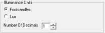
|
Enabled/Y |
Indicates the current illuminance unit is footcandles. You may convert between lux and footcandles without recalculating. Note: Exitance values are based on the Illuminance Units chosen in System Settings, not on the Display Units. If the Illuminance units are FC, Exitance values will be displayed in Lumen / Sq. Feet. If the Illuminance units are Lux, Exitance values will be displayed in Lumen / Sq. Meter |
|||
|
Lux |
Disabled/Y |
Indicates the current illuminance unit is lux. Note: Exitance values are based on the Illuminance Units chosen in System Settings, not on the Display Units. If the Illuminance units are FC, Exitance values will be displayed in Lumen / Sq. Feet. If the Illuminance units are Lux, Exitance values will be displayed in Lumen / Sq. Meter |
||
|
Number of Decimals |
1/N |
Indicates the display precision. The range is from 0 to 4. Level 0 rounds each calculated value to whole numbers (e.g., 0, 1,10, 100, etc.). Level 1 rounds each calculated value to a decimal place of 1 (e.g., 0.2, 1.4, 10.2, 99.5, etc.). Level 2 rounds each calculated value to a decimal place of 2 (e.g., 0.15, 1.38, 10.23, 99.46, etc.). Level 3 rounds each calculated value under 100 to a decimal place of 3 (e.g., 0.148, 1.375, 10.234, 99.456, etc.). Level 4 rounds each calculated value under 100 to a decimal place of 4 (e.g., 0.1485, 1.3754, 10.2342, 99.4559, etc.). 3 and 4 decimal points of precision should be used with caution. Although this level of precision can be calculated in AGi32, it is nearly impossible to measure in the real world. When using 3 or 4 decimals points it may be necessary to reduce the text size of the calculation points to prevent the numbers from overlapping. Decimal places of precision of one or more are only available for calculated values under 100). Values over 100 will round to 0 decimal places of precision. |
||
|
||||
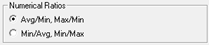
|
Avg/Min, Max/Min |
Enabled/Y |
Displays the numerical ratios using Average/Minimum and Maximum/Minimum nomenclature. This is the typical convention in North America. |
||
|
Min/Avg, Min/Max |
Disabled/Y |
Displays the numerical ratios using Minimum/Average and Minimum/Maximum nomenclature. Some international countries use this convention instead. |
||
|
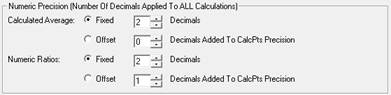
||||
|
Calculated Average - Fixed |
2 |
Displays the number of decimals that will be applied to ALL calculated averages. |
||
|
Calculated Average - Offset |
unselected. setting=0 |
Adds the set number of decimals to ALL calculated averages. |
||
|
Numeric Ratios - Fixed |
2 |
Displays the number of decimals that will be applied to ALL calculated ratios, Coefficient of Variation (CV) and Uniformity Gradient (UG). |
||
|
Numeric Ratios - Offset |
unselected, setting=1 |
Adds the set number of decimals to ALL calculated ratios, Coefficient of Variation (CV) and Uniformity Gradient (UG). |
||
|
||||
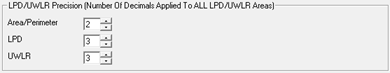
|
Area/Perimeter |
2 |
Displays the number of decimals that will be applied to ALL calculated LPD and UWLR perimeter lengths and areas. |
||
|
LPD |
3 |
Displays the number of decimals that will be applied to ALL Lighting Power Density calculations. |
||
|
UWLR |
3 |
Displays the number of decimals that will be applied to ALL Upward Waste Light Ratio calculations. |
||
|
||||
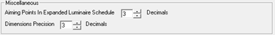
|
Aiming Points In Expanded Luminaire Schedule |
3 |
Displays the number of decimals that will be applied to luminaire aiming points in the Expanded Luminaire Schedule. |
||
|
Dimension Precision |
3 |
Displays the number of decimals that will be applied to ALL Dimensions. |
||
The Display/Project tab provides default View and Project parameters used in AGi32. Settings other than Default Colors are only used during start up, and changes are not applied in the current job file. To make changes, select the Save Settings as Startup Defaults option.
|
Setting |
Default Value / Included in Job File (Y or N) |
Description |
||
|---|---|---|---|---|
|
||||
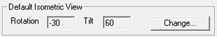
|
Rotation |
-30/N |
The rotation angle applied to the current view when the Default Isometric View command is selected. To change the Rotation angle click the Change button. |
||
|
Tilt |
60/N |
The tilt angle applied to the current view when the Default Isometric View command is selected. To change the Tilt angle click the Change button. |
||
|
||||
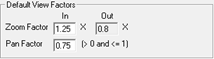
|
Zoom Factor |
1.25/N |
The Zoom In / Out Factor controls the amount the display is decreased / increased when a user Zooms In / Zooms Out using the Zoom In and Out commands. For example: If the current screen display width is 100’, and the Zoom In Factor is 1.25, the display width will decrease to 80’ when the user zooms in. |
||
|
Pan Factor |
0.75/N |
The Pan Factor controls the percentage amount a display is panned (in terms of screen width/height) when a user pans left, right up or down. For example: If the current screen display width is 100’, and the Pan Factor is 0.75, panning left will shift the display 75’ to the left. |
||
|
||||
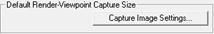
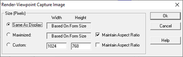
| Select button | Same As Display | This sets the default size of your render viewpoint captures for Reports. The Custom setting in the dialog allows a size of your choosing that may be smaller than Display or Maximized. | ||
|
||||
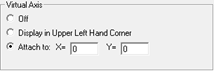
|
Off |
N |
Disables the Virtual Axis from displaying. |
||
|
Display in Upper Left Corner |
N |
Displays the Virtual Axis in the upper left corner of each view, regardless of coordinate display. |
||
|
Attach To |
Enabled, attached to origin (X=0, Y=0)/N |
Attaches the Virtual Axis to the origin. The virtual axis is a 3D indicator showing coordinate axes. It does not appear in output. |
||
|
||||
|
Frozen Entity Color |
Purple; checked by default/N |
The color applied to entities within a Frozen project. If unchecked, frozen entities are drawn using their normal color. |
||
|
Locked Luminaire Color |
Yellow-gray; unchecked by default/N |
The color applied to luminaires that have been Locked. If unchecked, locked luminaires are drawn using their normal color. The Locked Luminaire Color is NOT applied when exporting to CAD. |
||
|
Switched Off Luminaire Color |
Red; unchecked by default/N |
The color applied to luminaires that have been Switched Off. If unchecked, luminaires are drawn using their normal color. If both Locked and Switched Off Color are selected, Switched Off Color is used. The Switched Off Luminaire Color is NOT applied when exporting to CAD. |
||
|
Selected Entity Color |
Dark Gray/N |
The color applied to entities when selected within a command. |
||
|
Move Entity Color |
Medium Gray/N |
The color applied to the previous position of a Drawing entity, Room or Object that is being moved. |
||
|
Measure Distance/ Area Color |
Red/N |
The color of the polyline displayed during the Measure Distance and Measure Area commands. |
||
|
Temporary On Color |
Red/N |
The color applied to removed calculation points when the Replace Points command is selected. |
||
|
Calc Areas Text Color |
Red/N |
The color applied to Calculation Labels in the Statistics window. This color assists in identifying the summary type. |
||
|
Stat Areas Text Color |
Blue/N |
The color applied to Statistical Area Labels in the Statistics window. This color assists in identifying the summary type. |
||
|
LPD/UWLR Areas Text Color |
Green/N |
The color applied to LPD and UWLR Area Labels in the Statistics window. This color assists in identifying the summary type. |
||
|
Model Mode Background |
White/Y |
The Model Mode Background color indicates the color of the graphics area in Model Mode. The default color for the graphics area is controlled by the Window setting in Windows Display Properties dialog and is normally White by default. The Model Mode Background color is modifiable independently of the Windows setting by clicking in the Color cell and selecting an alternate color (e.g., black, blue, gray, white, etc.). There is no need to change any other colors when changing the background color since AGi32 automatically maps entity colors to keep them from disappearing. For example, when using a black background, black entities are automatically mapped to white to prevent them from disappearing. Whether or not an entity will 'flip' color will depend on the current Flip Color Tolerance parameter specified in Advanced System Settings. |
||
|
||||
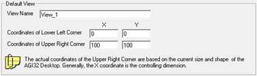
|
View Name |
View_1/N |
The default View Name is assigned to the initial view when a job file is opened. The View Name may not contain the characters: *, ?, or . |
||
|
Coordinates of Lower Left Corner |
X=0, Y=0/N |
The lower left coordinates of the initial view. |
||
|
Coordinates of Upper Right Corner |
X=100, Y=100/N |
The upper right coordinates of the initial view. The applied coordinates of the upper right corner depend on the size and shape of the view and AGi32 desktop. |
||
|
||||
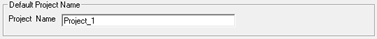
|
Project Name |
Project_1/Y |
The default Project Name is assigned to the initial project when a job file is opened. The Project Name may not contain the characters: *, ?, or . |
||
|
Setting |
Default Value / Included in Job File (Y or N) |
Description |
||
|---|---|---|---|---|
|
||||
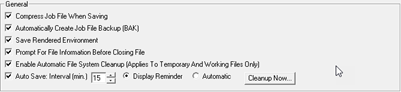
|
Compress Job File When Saving |
Enabled/Y |
The Compress Job File When Saving option compresses the saved job file to a size typically 3-6 times smaller than the original file size. |
||
|
Automatically Create Job File Backup (BAK) |
Enabled/Y |
By default, AGi32 creates a backup file (*.BAK extension) of the previous saved job file. Users may elect not to save a BAK file, however, this not recommended. |
||
|
Save Rendered Environment |
Enabled/Y |
By default, the Rendered Environment is saved when the job file is saved. AGi32 will ask if you wish to save the rendered environment when closing the current job file as long as this option is disabled. When a rendered environment is saved, a separate Radiosity Solution File is saved containing the rendered elements within the environment. The Radiosity solution file may be quite large, up to several megabytes. To save the Rendered Environment whenever the job file is saved, enable this option in the System Settings command (File System tab). The Radiosity Solution File will carry an RSF extension and will be saved in the same folder as the job file. Saving the rendered environment for large applications with many surfaces may be time extensive; therefore, AGi32 reports the save status on its command line to indicate progress. The AGi32 button on the Windows taskbar will also change its caption to AGi32-Saving as a visual clue if you are working on other applications at the same time. Finally, while the rendered environment is being saved, AGi32 is assigned 'below normal" priority so that you may open and work in other applications at the same time. |
||
|
Prompt For File Information Before Closing File |
Enabled/Y |
By default, AGi32 prompts for File Information when a file is saved for the very first time, when the Save As command is invokes or when AGi32 is closed, if the file has changed since the previous save. The File-Information command includes more information regarding what information is entered at this time. |
||
|
Enable Automatic File System Cleanup |
Enabled/N |
When enabled, user is prompted to perform File System Cleanup every 30 days. Files deleted during Automatic Cleanup include:
Only files more than five days old are deleted. |
||
|
Auto Save |
Enabled, Interval 15 Minutes, Display Reminder enabled/N |
Auto Save prompts you to save your file (or saves automatically) when enabled. You may specify the interval between Auto Save appearances. The default value is 15 minutes - it may be increased to 60 minutes. The option is also offered to display a reminder or save automatically. |
||
|
Cleanup Now... |
[Button]/N |
When selected, runs the File System Cleanup as described above. Provided as an alternative to waiting for the automatic cleanup. |
||
|
||||
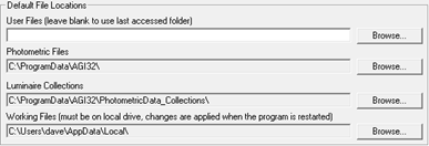
|
<blank> |
Default location for AGi32 Job Files. Leave blank to use the last accessed folder. |
|||
|
Photometric Files |
C:\ProgramData\AGi32\ |
Root folder location for photometric data; downloaded and extracted from Instabase and from transported Job File. To share files on a network, specify a centralized folder location on network server. |
||
|
Luminaire Collections |
C:\ProgramData\AGI32\PhotometricData_Collections\ |
Root folder location for luminaire Collections. This can be changed to a network resource to be shared with others (See Options below). The Reset to Default button also prompts for the same options. |
||
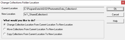
|
Options when changing Collections folder |
|
When electing to change the location of Luminaire Collections there are three options: 1. Simply change the location where Collections can be found. Your current Collections remain in the old location. 2. Move all of your existing Collections to a new location. 3. Copy all of your current Collections to the new location. |
||
|
Working Files |
C:\Users\<UserName>\AppData\Local\ |
Root folder location for all AGi32 related working and temporary files. This folder MUST be on the local drive (same drive on which program is installed). Working Files (including Render working files and temporary job files) must be stored on the same drive as the program (generally C:\), not in a network location. The default location will depend on which edition of Windows is installed. The location may be changed, but the new location will not be applied until the next time that AGi32 is started up. |
||
| Reset to Default buttons | Any of the above can be immediately reset to the factory default locations by clicking the adjacent button. The OK button is not necessary to carry out this action. | |||
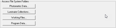
Access File System Folders |
|
|||
| Photometric Data... | Opens the root Photometric Files folder (specified above). | |||
| Luminaire Collections | Opens the PhotometricData_Collections folder or the user preference specified above. | |||
| Working Files... | Opens the root Working Files folder (specified above). | |||
| ProgramData... | Opens the root AGi32 ProgramData folder, which contains all of the program related files (e.g. symbols, arrangements, object libraries, etc.). One possible use of this folder would be to add new files to your system. For example: If you have an Object Library created by another user, you could add it to your system by opening this folder and placing the file. (.OBL) in the ObjectLibraries subfolder. | |||
Luminaire Attributes - Grid Tab
|
Setting |
Default Value / Included in Job File (Y or N) |
Description |
|---|---|---|
Attributes |
|
|
|
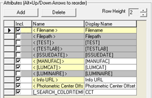
Add button |
|
Adds a new Attribute row to the list below. Check the box to include an Attribute in the Define dialog tile section. Check the box in the Columns to Display in Grid area to include in your define grid. See Attributes topic for information about creating new Attributes. Yellow Attributes are factory supplied. |
|
Delete button |
|
Deletes the selected row(s) from the Attributes list. You must select the row(s) to be removed before clicking the button. |
| Row Height | 2  |
The default Row Height is 2 (lines of text) when it appears in the Define dialog. |
Columns to Display in Grid |
|
|
|
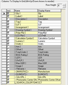
Row Height |
4 |
The default Row Height when adding an Attribute to the grid in the Define dialog is 4 lines. Check the box in the Columns to Display in Grid area to include in your define grid. See Attributes topic for information about creating new Attributes. Yellow Attributes are factory supplied. |
Luminaire Dialog Tab
|
Setting |
Default Value / Included in Job File (Y or N) |
Description |
|---|---|---|
Default Luminaire Symbols |
|
|
|
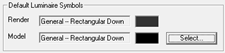
Model |
General - Rectangular Down/N |
The default luminaire symbol used in Model Mode. Click the Select button to specify an alternate Model symbol as the default. This symbol may be changed by invoking the Luminaire Symbols dialog while defining the luminaire. However, if one symbol is used more than others, you may wish to specify it as the default Model luminaire symbol.
A default wireframe color can be selected by clicking in the color cell. |
|
Render |
General - Rectangular Down/N |
The default luminaire symbol used in Render mode. Click the Select button to specify an alternate Render symbol as the default. This symbol may be changed by invoking the Luminaire Symbols dialog while defining the luminaire. However, if one symbol is used more than others, you may wish to specify it as the default Render luminaire symbol.
A default symbol color can be selected by clicking in the color cell. |
Smart Symbols |
|
|
|
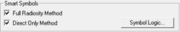
Full Radiosity Method |
Enabled/N |
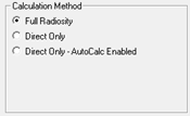
This setting enables the Smart Symbol selection routine when the Full Radiosity Method is applied, to be applied when photometric files are selected in the Luminaire Definition dialog. Smart Symbols automatically recommend a symbol for the selected photometric file using the luminous shape and dimensions specified in the photometric file along with the luminaire distribution. |
|
Direct Only Method |
Enabled/N |
This setting enables the Smart Symbol selection routine when the Direct Only method is applied (with / without AutoCalc enabled), to be applied when photometric files are selected in the Luminaire Definition dialog. |
|
Symbol Logic |
N |
The Symbol Logic button provides access to the Symbol Logic dialog. This dialog specifies which luminaire symbols are displayed when photometric files are selected. The symbol logic is based on photometric characteristics, luminous area size and shape and mounting options. |
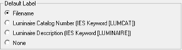
Default Label |
|
|
|
Filename |
Enabled |
AGi32 will use the IES filename as the default label when Automatically Define is enabled. |
|
Luminaire Catalog Number [LUMCAT] |
|
When selected, AGi32 will use the response to the [LUMCAT] keyword from the IES file as the Label. |
|
Luminaire Description [LUMINAIRE] |
|
When selected, AGi32 will use the response to the [LUMINAIRE] keyword from the IES file as the Label. Caution, this can result in very long labels. |
|
None |
|
When selected, you will be required to enter your own Label and the Automatic Definition process is interrupted. |
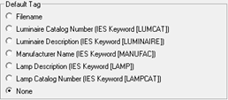
Default Tag |
|
|
|
Filename |
|
AGi32 will use the IES filename as the default label when Automatically Define is enabled. |
|
Luminaire Catalog Number [LUMCAT] |
|
When selected, AGi32 will use the response to the [LUMCAT] keyword from the IES file as the Tag. |
|
Luminaire Description [LUMINAIRE] |
|
When selected, AGi32 will use the response to the [LUMINAIRE] keyword from the IES file as the Tag. |
|
Manufacturer Name [MANUFAC] |
|
When selected, AGi32 will use the response to the [MANUFAC] keyword from the IES file as the Tag. |
|
Lamp Description [LAMP] |
|
When selected, AGi32 will use the response to the [LAMP] keyword from the IES file as the Tag. |
|
Lamp Catalog Number [LAMPCAT] |
|
When selected, AGi32 will use the response to the [LAMPCAT] keyword from the IES file as the Tag. |
|
None |
Enabled |
The Tag field is left blank. |
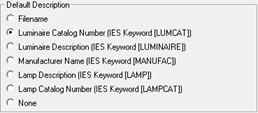
Default Description |
|
|
|
Filename |
|
AGi32 will use the IES filename as the default label when Automatically Define is enabled. |
|
Luminaire Catalog Number [LUMCAT] |
Enabled |
When selected, AGi32 will use the response to the [LUMCAT] keyword from the IES file as the Description. |
|
Luminaire Description [LUMINAIRE] |
|
When selected, AGi32 will use the response to the [LUMINAIRE] keyword from the IES file as the Description. |
|
Manufacturer Name [MANUFAC] |
|
When selected, AGi32 will use the response to the [MANUFAC] keyword from the IES file as the Description. |
|
Lamp Description [LAMP] |
|
When selected, AGi32 will use the response to the [LAMP] keyword from the IES file as the Description. |
|
Lamp Catalog Number [LAMPCAT] |
|
When selected, AGi32 will use the response to the [LAMPCAT] keyword from the IES file as the Description. |
|
None |
|
The Description field is left blank. |
Default Tag |
|
|
|
Filename |
|
AGi32 will use the IES filename as the default label when Automatically Define is enabled. |
|
Luminaire Catalog Number [LUMCAT] |
|
When selected, AGi32 will use the response to the [LUMCAT] keyword from the IES file as the Tag. |
|
Luminaire Description [LUMINAIRE] |
|
When selected, AGi32 will use the response to the [LUMINAIRE] keyword from the IES file as the Tag. |
|
Manufacturer Name [MANUFAC] |
|
When selected, AGi32 will use the response to the [MANUFAC] keyword from the IES file as the Tag. |
|
Lamp Description [LAMP] |
|
When selected, AGi32 will use the response to the [LAMP] keyword from the IES file as the Tag. |
|
Lamp Catalog Number [LAMPCAT] |
|
When selected, AGi32 will use the response to the [LAMPCAT] keyword from the IES file as the Tag. |
|
None |
Enabled |
The Tag field is left blank. |
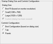
Startup Dialog Size and Controls Position |
|
|
|
Dialog Size |
Best Fit (based on monitor resolution) |
Dialog size is maximized to accommodate all Panels and as much grid space as possible adjusting for the monitor resolution. On larger monitors this is often the same as Large. |
|
|
Small (1290 x 768) |
Dialog size is reduced to operate on laptop computers and lower resolution monitors. Not all columns in the grid may be visible (it may scroll LR) and Panels will be stacked vertically in a scrolling column. |
|
Default |
Large (1920 x 1200) |
Dialog size is maximized t eliminate scrolling in grid and Panels. Grid may scroll depending on the number of columns selected for display. |
|
|
Custom (dialog has been resized by user) |
When dialog has been resized manually it will retain those dimensions and the setting will appear as Custom. |
|
Controls Configuration |
Best Configuration (based on dialog size) |
Dialog will decide between tabbed or scrolling panels on the right side based on available width. |
|
|
Tab |
Right side dialog inputs will be organized into two or three tabs depending on Dialog size selected. |
|
|
Panels |
Right side dialog inputs will be organized into one or two columns depending on Dialog size selected. |