The Advanced Settings dialog provides access to advanced parameters used in AGi32. Users should NOT modify these settings unless they know what they are doing or have been instructed to do so by Lighting Analysts product support. Modified settings will only impact the current job file unless the checkbox is enabled to Save Settings as Startup Defaults.
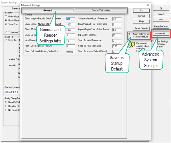
Reset Defaults Button- Resets all the advanced settings to the factory provided settings.
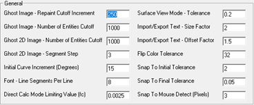
General Tab
The General Tab provides Advanced parameters related to working with AGi32's model area and importing files.
Render/Calculation Tab
The Render tab provides Advanced parameters related to AGi32 meshing parameters and advanced calculation settings.
|
Setting |
Default Value / Included in Job File (Y or N) |
Description |
|---|---|---|
|
Initial Meshing |
|
|
|
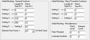
Initial Meshing - General Surface Types |
Setting 1: Length=8, Patch Size=2/Y Setting 2: Length=32, Patch Size=4/Y Setting 3: Length=128, Patch Size=8/Y Setting 4: Length=384, Patch Size=12/Y Setting 5: Length>Setting 4, Patch Size=16/Y Element Size Factor=0.5/Y |
This section specifies the initial discretization of all surfaces in rooms and objects and Diffuse Window Transition surfaces. The mesh level is based on the longest side of each surface. Decreasing the patch size increases the number of patches and elements and lengthens the calculation time, may increase accuracy. |
|
Initial Meshing - Glass/Transition Surface Types |
Setting 1: Length=8, Patch Size=2/Y Setting 2: Length=16, Patch Size=2/Y Setting 3: Length>Setting 2, Patch Size=4/Y |
This section specifies the initial discretization of Transparent Window and Daylight Opening Transition surfaces. The mesh level is based on the longest side of each surface. Decreasing the patch size increases the number of patches, lengthens the calculation time and may increase accuracy. Note: Only Patches are used in these Transition surface types, Elements are not included (reflected light is not considered). |
|
Initial Meshing - Miscellaneous |
Pole/Pendant: Patch level=0, Element level=1/Y Luminaire symbols: Patch level=0, Element level=1/Y |
This section specifies which patch and element levels (from the Variable section) to use when discretizing poles, pendants and luminaire symbols. |
|
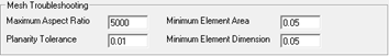
Mesh Troubleshooting |
|
|
| Maximum Aspect Ratio | 5000/Y | If the length-to-width ratio of a bounding box enclosing a surface exceeds the maximum aspect ratio, the meshing parameters for the surface will be forced to 0:0. The default ratio is 5000:1 (entered as 5000). NOTE: these parameters can be used to prevent numerical stability problems that results in meshing artifacts or parsing failure. They should not be changed unless instructed to do so by Lighting Analysts staff. |
| Minimum Element Area | 0.05/Y | The minimum element area specifies the smallest acceptable element area for which the specified meshing parameters will be applied.. |
| Planarity Tolerance | 0.01/Y | If the vertices representing the surface are not coplanar to within the planarity tolerance, the meshing parameters for the surface will be forced to be 0:0. |
| Minimum Element Dimension | 0.05/Y | The minimum element dimension specifies the smallest acceptable element dimension for which the specified meshing parameters will be applied.. |
|
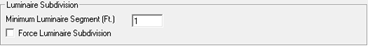
Luminaire Subdivision |
|
|
|
Minimum Luminaire Segment |
1/Y |
This setting allows you to specify the maximum discretization level for luminaires. The default value is 1 foot. Point sources are not discretized. By default, luminaire subdivision occurs based on closest element proximity. If luminaires subdivision is forced (see row below), all luminaires are subdivided when applicable regardless of surface geometry. Luminaire Subdivision only occurs when there are room and/or object surfaces defined (surfaces must be on - not Frozen, Removed or Off in Project Manager). |
|
Off/Y |
This setting forces luminaire to subdivide to specified size regardless of surface proximity. Subdivision occurs along and across the luminous box producing a rectangular array of sources. The absolute maximum number of subdivisions for each luminaire is 16 in each direction regardless of specified size, this results in a maximum of 256 sources (16x16). For example, if the Luminaire Subdivision value were set to 0.1, a four foot by one foot luminaire would only be subdivided into 0.25 foot pieces (4/16). The subdivision level applied along the maximum dimension is also applied to the opposite dimension so that a point source summarizing a box is created. This option should be used with caution, as forcing luminaire subdivision will increase calculation time particularly when raytracing direct illumination. Luminaire subdivision increases the number of luminaires, which increases calculation time. |
|
|
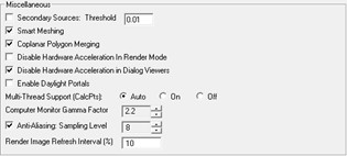
Miscellaneous |
|
|
|
Secondary Sources |
Off/Y 0.01/Y |
Secondary light sources (secondary sources) reduce the occurrence of surface mottling which can occur by light emitted from bright patches to small elements. Secondary sources are disabled by default. When enabled, secondary sources are ‘activated’ only if both of the following situations occur:
When these conditions exists, the first bounce of light from the patches that meet these requirements will be ray traced to the elements, instead of being calculated by radiosity algorithms. Ray tracing secondary sources can increase calculation times significantly, as the number of steps increases; however, the visual results are more aesthetically appealing and smoother than mottled surfaces. Each additional secondary source ray trace will add an additional step to the total radiosity calculations. Users can tell if a secondary source calculation occurred by comparing the number of steps in the Calculation Summary dialog with and without secondary sources enabled.
These situations may require a necessary decrease in the Secondary Sources Threshold value
Note: Secondary Sources are also applied to Direct Flux Only surfaces when enabled, except for Roadway pavement surfaces. To utilize a Direct Flux Only surface as only considering Direct Flux, Secondary Sources must be disabled. |
|
On/Y |
This setting specifies how surfaces with Automatic Placement calculation points are meshed. Surfaces with Automatic Placement points are meshed finer than surfaces without points. Note: Only General Surface Types respond to Smart Meshing. |
|
|
Coplanar Polygon Merging |
On/Y |
Coplanar Polygon Meshing is the process where surfaces that lie in the same plane, in the same object, with the same properties are 'merged' into a single surface. This reduces the number of surfaces and minimizes shading discontinuities between adjacent surfaces. This process may produce undesirable or unexpected results when the merged surfaces have different initial mesh properties (resultant mesh may be less than expected). If this occurs, simply disable coplanar polygon merging. |
|
Disable Hardware Acceleration Render Mode |
False (Not Selected)/Y |
Hardware Acceleration can affect the appearance of the rendered environment. Sometimes changing this setting will improve the image. |
|
True (Selected)/Y |
Hardware Acceleration can affect the appearance of the graphics in some dialogs, such as Roadway Optimizer and the CAD Viewer. Sometimes changing this setting will improve the image. |
|
|
Enable Daylight Portals |
False (Not Selected)/Y |
If enabled, Transition Surfaces are treated as Daylight Portals. This currently has no effect on the calculations. Daylight Portals will be implemented in a future release. |
|
Multi-Thread Support (CalcPts) |
Auto/Y |
Multi-Thread processing is available for the following calculation types when using Full Radiosity Method: Virtual Meter Illuminance, Daylight Factor, and UGR. Multi-Thread processing is not available with Direct Only Method or with the following calculation types: Exitance Meter Illuminance, Exitance, and Luminance For computers with two or fewer available threads, engaging Multi-Thread processing may actually increase the calc time. Therefore, AGi32 first checks the number of available threads and then proceeds with the calculations based on which of these settings is selected:
|
|
2.2/Y |
The Gamma Factor adjusts for the non-linearity of phosphor excitation in computer monitors. A computer monitor displays colors by exciting phosphors on the screen. Since phosphors are not excited linearly, when the computer reads a luminance value from the rendered image and sends it directly to the monitor the displayed luminance will be less than the calculated luminance. The actual Gamma Factor varies between makes and models of monitors but in general, a value of 2.2 is used. |
|
|
Anti-Aliasing Sampling Level |
8, Enabled by chec kbox (True)/Y |
The Anti-Aliasing Sampling Level allows the user to automatically apply anti-aliasing to the rendered images in Render Mode. Anti-aliasing is a software technique used to make jagged edges in images appear smoother. By overlaying the original images with slightly offset copies, the eye is fooled into seeing straighter lines and smoother curves (instead of “jaggies”). The Sampling Level indicates the number of image copies applied and offset from the original image.
Anti-Aliasing is enabled by default (check box) and set to 8 samples. The Maximum Sampling Level is 15. Higher sampling levels increase the image quality but also take longer to produce. |
|
Render Image Refresh Interval |
10/Y |
Indicates the percentage change in light absorption at which the display is refreshed during the radiosity calculations. The default value is 10%. At this interval, the display is refreshed whenever the Light Absorbed value increases by 10% from its previous level, starting from the amount initially absorbed (e.g. 30, 33, 37, 41, 45, 50, etc.). Note: When calculating in Model mode, the render image is never directly displayed, hence the refresh interval does not apply. Calculating in Model mode will be slightly faster than calculating in Render mode, because the display does not require refreshing. |