
![]()
Ray Trace Parameters
The Ray Trace Parameters dialog is used to specify the parameters used to generate Ray Trace images in AGi32.
From
the Control Bar select ![]() . To modify the Raytrace parameters,
choose the Set Parameters option from the Raytrace secondary menu.
. To modify the Raytrace parameters,
choose the Set Parameters option from the Raytrace secondary menu.
General tab
Number of Bounces
This value indicates the maximum number of specular bounces for each ray. The default value is 3, which is adequate for most environments. Environments with many specular or transmissive surfaces may require an increase in the number of bounces to ensure consideration of all specular bounces.
Note: Increasing the number of bounces will increase calculation time.
This value indicates the Anti-Aliasing level applied to the Ray Trace images. The Default value is 0; no Anti-Aliasing is applied. Anti-Aliasing minimizes the appearance of jagged edges in the Ray Trace images. Anti-Aliasing is achieved in the Ray Trace process by tracing additional rays to the corners of each pixel. This process can dramatically increase calculation time; however, the image quality may be greatly improved.
With Anti-Aliasing level equal to zero, the Ray Trace process starts by tracing four rays to the corners of each pixel. With Anti-Aliasing applied, (N + 1)2 additional rays are required (where N equals the Anti-Aliasing level). These additional initial rays may in turn spawn additional rays.
|
Anti-Aliasing level |
Initial rays to each pixel |
|---|---|
|
0 |
4 |
|
1 |
8 |
|
2 |
13 |
|
3 |
20 |
|
4 |
29 |
|
5 |
40 |
Ray Trace All Defined Viewpoints
When enabled, this parameter creates Ray Trace images for all defined Viewpoints. This parameter is disabled by default.
Note: To create a series of Ray Trace images (e.g., for walk-throughs), it is very efficient to set up multiple Animation points using the Render-View-Animation points command first. You may also ray trace an animation when creating a movie file (see Creating Movie Files)
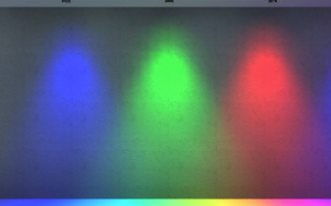
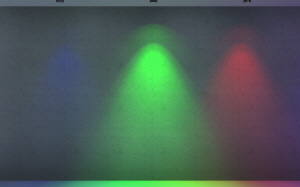
Ray Trace Direct Illumination
When enabled, the Direct Illumination from all specified light sources (Daylighting and Electric Lighting) is ray traced. Forward Ray Tracing, as this method is labeled, displays distinctive or harsh shadow lines or scalloping on surfaces as a result of Direct Illumination. This setting is enabled by default, and is always enabled for daylighting when there is a direct-sun contribution.
Be aware, that enabling Direct Illumination, specifically with Electric Lighting sources, can be very time consuming and may increase your calculation times significantly. The Ray Trace calculation time will increase in proportion to the number of light sources. As such, you may want to limit it to final image generation (e.g., presentation images).
Ray Trace Direct Illumination may also illuminate the surfaces of your luminaire symbol as well. In Ray Trace calculations, all surfaces are double sided and seen by the rays. If you experience scalloping on the luminaire surfaces, you may need to decrease your Luminaire Subdivision Level (discretize it into smaller pieces) in Advanced System Settings and recalculate (both Radiosity and Ray trace).
|
|
|
Glossy Surfaces - When enabled, this parameter ray-traces Glossy Surfaces as defined in the AGi32 job file. The Glossy Surface attribute is applied individually to surfaces using the Surface Edit command. Only surfaces with Specularity assigned will have Glossiness applied, if a Glossiness value greater than zero is defined.
Note: Glossy Surfaces require more rays to be traced from each specular surface intersection. Calculation times will increase on average up to 3 - 5 times longer than without Glossy Surfaces enabled.
Soft Shadows - When enabled, this ray trace technique traces the soft shadows created by the boundary of the luminous areas described in AGi32.
Note: Calculation times will increase on average up to 10 - 15 times longer with Soft Shadows enabled.
Combining Soft Shadows and Glossy Surfaces into a ray-trace calculation may increase your calculation times by a factor up to 100. It is strongly recommended to limit the use of soft shadows and/or glossy surfaces for presentation grade images only.
This value indicates the level of Tone Mapping compression applied to ray traced images so that they may be displayed more naturally on a computer monitor, which has a low dynamic display range (255:1). Tone Mapping is typically used to convert the high tones of an image into lower tones (i.e., "dodge the highlights," in photographic terms). Tone mapping may also be used to convert the low tones to higher ones (i.e., "burn the shadows," in photographic terms).
|
Tone Mapping Compression level |
Effect |
|---|---|
|
0-1 |
Convert low tones to higher tones |
|
1-10 |
Convert high tones to lower tones |
- Tone mapping effects are most noticeable when one is creating an image looking out of an interior environment opening or window and viewing the exterior environment.
Generated Images
Image Size (Pixels)
This section specifies the size of the generated Ray Trace images in pixels. Two options are provided for selection:
- Same As View Display Size - This option generates Ray Trace images that are the same size as the specified Render views. If the Ray Trace All Defined Viewpoints option is specified, the generated Ray Trace images will be the same size as the current view. Note: Image size is dependant on Actual View size, aspect ratio and screen resolution.
- Custom - This option allows you to generate Ray Trace images that are of any desired size, independent of the specified render view sizes or current screen resolution. This option allows you to generate large images for desktop publishing or choose small images for quick Ray Trace analysis.
- To generate custom image sizes, specify either the Width or Height of the desired images. The other dimension will be automatically sized to maintain the original View aspect ratio.
- Generating large image sizes requires more memory and will increase processing times.
This section allows generation of a Fisheye view rather than the Normal (default) view. Fisheye images are like those seen with an ultra-wide-angle lens. The images are visually distorted to create a wide panoramic or hemispherical image. The acceptable range is 45 to 360 degrees, with 180 degrees being the default.
Format
This section indicates whether the generated Ray Trace images are saved as Bitmap (BMP), JPG, PNG, or High Dynamic Range (HDR) files.
JPG vs BMP - JPG images use lossy compression to generate smaller file sizes with fairly high quality. Generally speaking, for screen presentations,you will have a hard time differentiating between BMP and JPG images, and should use the JPG format for output. For desktop publishing, where large image sizes are typically desired, the Bitmap file format is preferred. The BMP files contain the raw pixel data, with no applied compression. The default setting is JPG.
- What is Lossy compression? It is a compression technique that eliminates redundant pixel information in order to generate smaller file sizes. AGi32 applies a high quality compression algorithm to maintain the best quality images while reducing file sizes. For example, bitmap files requiring 1.8 Mb of disk space are compressed to less than 200 Kb (10% of their original size).
High Dynamic Range (HDR) files - HDR images require a special program/viewer (e.g., Photoshop, HDRView). However, the images are really not meant to be viewed directly. The primary purpose is to encode the actual spectral radiant exitance in each pixel so that the image can be used for photometric analysis by tools like Matlab. In addition, HDR images enable users to perform whatever tone mapping operations they want using Photoshop or other similar program.
Fisheye HDR images are commonly used by daylight researches for evaluating daylight glare using the Radiance utility program evalglare. HDR files generated by AGi32 are fully compatible with LBNL's Radiance photometric analysis tools, including evalglare.
Location of Generated Images - • Location for Ray Trace Images is specified using the Tools-System Settings command (File System tab). The default location is: <JobFileFolder> \_RayTraceImages
Apply Cloud Image to Sky Dome (Only applicable with Daylighting)
This section provides for the selection of sky dome cloud images to be added to daylit environments for a more realistic ray-trace rendering presentation. In order to apply clouds: you must have applied daylighting and have the Sky Dome On in the Daylight Parameters dialog.
![]() Clouds are strictly cosmetic and have no effect on the
luminance values or calculated values of the AGi32 scene. The Sky Condition
and solar location specified in the Daylight Parameters dialog determine
the algorithms used to calculate daylighting; clouds are simply for visualizations
only.
Clouds are strictly cosmetic and have no effect on the
luminance values or calculated values of the AGi32 scene. The Sky Condition
and solar location specified in the Daylight Parameters dialog determine
the algorithms used to calculate daylighting; clouds are simply for visualizations
only.
Automatic Cloud Specification - The Cloud Parameters are automatically selected based on your current daylight sky condition. Three options are provided; each one allows you to vary your clouds based on your own preferences and regional sky conditions.
Manual Cloud Specification - This section provides for manual selection of the cloud parameters used to generate cloud images.
|
Cloud Parameters |
Description |
|---|---|
|
Coverage |
Specifies the approximate fraction of the sky dome that is covered by clouds (range: 0 – 1.0). |
|
Definition |
Specifies the definition (or ‘softness’) of the cloud boundary (range: 0 – 0.99). The higher the value, the more defined the cloud boundaries. |
|
Noise Slice |
Random number uses to generate a random distribution of clouds (range: 0 – 1.0). |
|
Whiteness |
Specifies the average ‘whiteness’ of the clouds (range: 0.25 to 2.0). The higher the value, the ‘whiter’ the clouds. Lower values may be useful with overcast skies to produce contrast between the clouds and the background sky dome. |