
Rectangular Rooms with a Barrel Vault Ceiling
- From the Add
menu select Room - Rectangular - Barrel Vault,
or from the Rooms/Objects Toolkit click the arrow adjacent to the Room - Rectangular
button
 . The secondary menu will appear. Select Barrel Vault.
 - Specify a unique label for the room up to 32 characters long. The default label will be Room_1. Unless changed, subsequent labels will be Room_2, Room_3, etc. If a number is used for the label, subsequent labels will be incremented accordingly.
- If desired, a description may be entered, up to 80 characters long. Meaningful descriptions including size and color will be useful for schedules.
- The room will be created in AGi32 using the selected Wire Frame Color. This color is not used in AGi32's render mode, it is only used to represent the room's shape in the graphics window. By default, this color is green. To change it, click in the color cell. The Color dialog will appear for your use.
- If surface labeling is desired, click on the Labeling button. A separate dialog will appear for specification of text labels for the room and/or its surfaces.
- Enter the height of the room walls in the Wall Height text box.
- Enter the barrel vault height above and beyond the room wall height in the Vault Height text box.
- Enter the barrel vault width in the Vault Width text box.
- All of the surfaces within the room are assigned a color. By default, the colors are made up of varying shades of gray corresponding to reflectance values of 0.8 (ceiling), 0.5 (walls) and 0.2 (floor).You may change the Reflectance by simply typing a new value in the Reflectance cell for the Ceiling, Walls or Floor. You may change the surface colors and their corresponding reflectances by clicking in the Color cell for the Ceiling, Walls or Floor. The Color Selection dialog will appear allowing you to select surface colors based on user defined reflectances.
- You may assign a texture to the surface by clicking in the Texture cell. The Select Texture dialog will appear so that you may choose a texture from the Textures database. Alternately, you may browse for a texture anywhere on your system or assign a texture already in use on another surface in the job file. Once the desired texture is selected, you'll determine how the texture should be applied to the surface. Textures may be stretched across the entire surface, applied in a grid pattern or assigned a Static size (representing real dimensions) and tiled on the surface accordingly. In addition, you may opt to rotate the texture on the surface.
To delete a texture from the surface, Ctrl-click in the Texture cell and select the Delete key on your keyboard. When a texture is deleted from a surface, its correlated color and reflectance are used as the current color and reflectance.
- To apply additional surface properties (such as Texture, Transmittance, Transparency, Luminance, Specularity, Color Bleed control or surface specific Mesh Levels) to any of the object surfaces, you must first position the room in the environment. Then, either Edit the room and select the Surface Edit button in the Edit dialog or use the Surface Edit command to select the object.
- Removing Surfaces - Removing surfaces allows you to append other surfaces to factory defined shapes and create more complex models. Surfaces may be removed by Editing the room or using the Surface Edit command once it has been placed.
- By default, rooms are composed of single-sided surfaces, facing inward. This attribute allows you to see into the room without having to walk inside in Render mode. You may flip the surface direction or change the surface type to two-sided in the Surface Edit command as well. Important: See Adding Rooms - Concepts (first section) for effect of single-sided surfaces on calculations.
- To open the ends of the barrel vaulted room, such as a tunnel application, click in the Ends of Room and Barrel Vault Are Open selection box so that a check mark appears. Rectangular barrel vault rooms with open ends only have two walls, perpendicular to the open ends.
- Additional Tasks (performed after creating Room):
- Specify Calculation Points (selected by default): After clicking OK, the Automatic Placement dialog will open, with the workplane selected for the calculation grid. You may change any settings and then click OK. You will be returned to the graphics window, where you can draw the room (see Step 13).
- Automatically Create LPD Area (not selected by default): If selected, an LPD Area will automatically be created, using the settings in the LPD/UWLR dialog. Exception: Creating an LPD Area this way sets the line color of the LPD Area to be the same as that of the Room for which it is being created. Clicking the Settings button opens the LPD/UWLR dialog, where you may set your preferences for this LPD Area.
- Click OK to return to the graphics window and
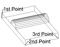
locate the first point of the room. Click the left mouse button. Before
clicking the first point, you will have the opportunity to change the
Z coordinate of the floor if desired. Move the cursor into the Z-Coord text box
and enter the appropriate value.
- Note: If the Z-Coord value is not equal to zero,a warning icon will be displayed to alert the user to this condition.
- Drag the cursor to the second point on a room edge and left click again. These two points define the room's baseline.
- Drag the cursor to open up the room perpendicular to the specified baseline and left click when the appropriate depth has been achieved. The room may be created on either side of the baseline. The barrel vault will also be created perpendicular to the specified baseline.