
![]()
Room shapes in AGi32 range from very simple geometry - rectangular rooms with flat ceilings - to complex spaces with unusual ceiling configurations, including domes, vaults, pyramids and custom ceilings. Rooms are intended to be used for interior lighting applications and may be located with base elevation at any level.
Room surfaces may be assigned a transmittance using the Surface Edit command once the room is created.
By default, rooms are created with "single-sided" surfaces, which obstruct light from leaving the room. Rooms are one-sided so that they may be viewed in Render Mode without the need to walk inside.
Important: Luminaires placed outside a room that are not within another room or blocked by an object may illuminate the interior of the room. Calculation points inside the room may be affected by luminaires located outside of the room that are not located in other rooms or blocked by objects.
Applying calculation points with Automatic Placement will place all related grids by default, on the inside of the room shape (the Normal side of this surface type).You may place points on the outside of the Room by placing points on the Abnormal side using Automatic Placement, or by flipping the surface normal inside using the Surface Edit command.
|
Rooms with ceilings of different heights can actually be handled by using multiple rooms and removing the shared surfaces, as shown at right. In fact, combinations of all types of room shapes make modeling interior lighting projects more realistic than ever. |
|
Dialog Defaults
The individual parameters available in all Room dialogs are automatically saved and restored in the Room dialogs. There are two types of defaults present in all of the dialogs: Global and Local. Global defaults occur in every Room dialog. Local defaults only occur in specific dialogs. The following defaults are global for all Room commands.
- Label: Default Label is Room. The Label name will automatically increment to produce unique labels. For example, if the first Room is labeled Room, the second is labeled Room_1. When the default label is changed, it will also automatically increment.
- Wireframe color
- Labeling options
- Wall Height
- Ceiling, Wall and Floor surfaces: Color, Reflectance and Texture (including applied options).
- Additional Tasks: Specify Calculation Points
Reset Defaults - Selecting this button will reset all Global dialog parameters to the factory-defined specifications.
Room Dimensions
All room types have certain dimensional variables associated that describe some parameter of the shape that must be defined prior to creating it in the graphics area.
|
|
|
|
|
|

|
|
|
|
|
|
|
|
|
|
|
|
|
|
Aspect ratio - The Aspect Ratio is used to define the shape of the round room footprint. An Aspect Ratio equal to one will create a perfectly round room footprint. Aspect Ratios greater than one lengthen the X-axis of the base resulting in an elliptical shape left to right. Aspect ratios less than one elongate the Y-axis of the base to form an ellipse aligned top to bottom. As an example, an Aspect Ratio equal to two will create an ellipsoidal room that is twice as long in the X-dimension as it is in the Y-dimension. An Aspect Ratio equal to one half (.5) will create an ellipsoidal room that is twice as long in the Y-dimension as it is in the X-dimension. |

Surfaces
Surface properties of Color and Reflectance must be defined for all rooms. When initially defining rooms, reflectance and color are expressed for the Ceiling, Walls and Floor. It is possible to edit the wall reflectances on an individual basis by editing the room.
Color and Reflectance are related to one another in a way that allows only certain colors to be assigned to a specific reflectance value. This is a mathematical relationship that is discussed in more depth elsewhere in this manual. To alter the color or reflectance of a room surface, click the mouse in either the color or reflectance cell.
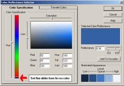 By default, the colors shown are shades of gray based
on the reflectance entered in the adjacent cell. You can select any reflectance
within the gray scale range (Black to white) by
entering it in the reflectance cell provided-
By default, the colors shown are shades of gray based
on the reflectance entered in the adjacent cell. You can select any reflectance
within the gray scale range (Black to white) by
entering it in the reflectance cell provided-
To select a color, move the Hue slider to the desired color, then move the Saturation and Luminance sliders to achieve the desired color. The reflectance will be calculated and displayed. You can adjust the reflectance within the Hue by moving the reflectance slider.
Textures
Textures are graphic images that may be applied to the room surfaces to make them appear more realistic. Textures like brick, stone, concrete and wood can be tiled in a repeating pattern across the surfaces or stretch across them. The average reflectance and color of the texture is calculated and used instead of the surfaces original color in the radiosity calculations.
AGi32 comes with a selection of assorted textures that may be applied to any surface. You may also obtain textures from lots of other sources, including free texture sites online, commercial texture collections, even use your digital camera to obtain them directly. Click here to read about texture tips.
To apply a texture to a surface, click in the Texture cell. Select the texture from the Texture database, then determine the application options.
Open-Ended Rooms
Certain rectangular room types, Rectangular-Barrel Vault and Rectangular-Vertical Extrusion, may be created with their extruded ends left open. This option allows you to use these rooms in an open fashion (i.e., model tunnels) or connect the rooms to other spaces.
Open Ends Option
When the Ends of Room Are Open option is selected, the extruded walls and ceiling end panels are removed. Open rooms may be closed at a later time by editing the room and unchecking the Ends of Room Are Open selection box.
Inserting curved surfaces into rooms (Polygon-Flat, Rectangular-Vertical Extrusion and Round-Vertical Rotation)
It is a simple procedure to describe a curved surface using an integrated Arc function. An arc can be fit between any two points and can be of most any radius. To insert an arc into a room, press the F4 key on your keyboard at the starting point of the arc. The command prompt (lower left corner of screen) will then prompt for the second point of the arc as shown at right. Click the mouse at the second point of the arc and a dotted line will appear showing the current arc shape. If you don't move the mouse the initial arc will be a perfect semi-circle (#1). Move the mouse cursor toward the arc apex to raise the arc center point and increase the circumference (#2).Or, move the cursor away from the apex of the arc and move the arc center downward. This effectively flattens the arc (#3).
Reversing the Arc
The direction of the arc can be reversed by simply pressing the F5 key on your keyboard.
Curved-surface resolution
Curved surfaces are automatically divided into a series of straight segments based on the setting of the system variable Initial Curve Increment (degrees). The default is 15 degrees. This is adequate for most applications. This variable can be found under System Settings command from the Tools menu. Click on the Defaults tab and then on the Advanced button.
Removing Surfaces
AGi32 provides the ability to eliminate surfaces from any room shape you might create by removing the surfaces. Removed surfaces are not considered in the calculations any longer. A removed surface behaves differently than one whose reflectance is set to zero. Surfaces that have zero reflectance absorb all light that touches them and reflect no light outwards. Removed surfaces allow light to transmit directly through them because they no longer exist (unless another surface exists in the same location). Once surfaces are removed, you can recreate them by adding in a surface with reflectance (either 1 sided or 2 sided).
By removing selected surfaces in the room, you have the ability to append other shapes to the room. These shapes (rooms, objects) may in turn have their surfaces removed. Continuing in this fashion, you can create very elaborate models consisting of numerous rooms and/or objects joined together. For example, you may want to create an Polygon-Flat room and remove the flat ceiling that was initially created. Once the ceiling is removed, you can use any combination of rooms and objects to create a custom ceiling.
To remove a surface, either Edit the room and select the Surface Edit button in the Edit dialog or use the Surface Edit command to select the room. In the Surface Edit dialog, navigate to the surface you wish to remove. To remove more than one surface in a room, Tag all of the surfaces you need to operate on. Change the Surface property titled Removed to YES.
The surfaces will be removed from the environment. In Model Mode, they will appear as dashed lines, in Render mode, they will simply not appear. Removed surfaces can be replaced at any time through the Surface Edit dialog by changing the surface Removed property to NO.