
Round/Elliptical Objects - Sphere
|
|
Spherical objects can be created in AGi32 quickly and easily. This object type may be completely or partially circular and can have an aspect ratio other than 1 applied to it so that it is elliptical, if desired. The aspect ratio defines the ratio of the left-right radius relative to the top-bottom radius of the object. A ratio = 1 produces a sphere. A ratio > 1 produces an ellipsoid in the left-right direction. A ratio < 1 produces an ellipsoid in the top-bottom direction. Partially circular spheres (i.e. hemispheres) may be open or closed as necessary. Open spherical objects may be reflective on the inside or outside, as desired. If the open sphere is transmissive, it is already reflective on both sides so this option is not applied. Once the specifications in the dialog have been completed, the object is created by locating the center point of the object (at the sphere’s center) and then dragging the cursor to specify the object's radius. |

- From the Add
menu select Object - Round/Elliptical - Sphere,
or from the Rooms/Objects Toolkit click the arrow adjacent to the Round/Elliptical
Object button
 . The secondary menu will appear. Select Sphere.
 - Specify a unique label for the object up to 32 characters long. The default label will be Object_1. Unless changed, subsequent labels will be Object_2, Object_3, etc. If a number is used for the label, subsequent labels will be incremented accordingly.
- If desired, a description may be entered, up to 80 characters long. Meaningful descriptions including size and color will be useful for schedules.
- The object will be created in AGi32 using the selected Wire Frame Color. This color is not used in AGi32's Render mode, it is only used to represent the object's shape in the graphics window. By default, this color is blue. To change it, click in the color cell. The Color dialog will appear for your use.
- If surface labeling is desired, click on the Labeling button. A separate dialog will appear for specification of text labels for the object and/or its surfaces.
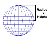
- Specify the height of the object:
|
|
|
|
- All object surfaces are assigned a color. By default, the surfaces are assigned a shade of gray corresponding to a reflectance value of 0.5. You may change the reflectance of a surface by simply typing a new value in the Reflectance cell for the Top, Sides, or Bottom. You may change surface color and its corresponding reflectance by clicking in the Color cell for the Top, Sides or Bottom.The Color Selection dialog will appear allowing you to select surface colors based on user defined reflectances.
- You may assign a texture to the surface by clicking in the Texture cell. The Select Texture dialog will appear so that you may choose a texture from the Textures database. Alternately, you may browse for a texture anywhere on your system or assign a texture already in use on another surface in the job file. Once the desired texture is selected, you'll determine how the texture should be applied to the surface. Textures may be stretched across the entire surface, applied in a grid pattern or assigned a Static size (representing real dimensions) and tiled on the surface accordingly. In addition, you may opt to rotate the texture on the surface.
To delete a texture from the surface, Ctrl-click in the Texture cell and select the Delete key on your keyboard. When a texture is deleted from a surface, its correlated color and reflectance are used as the current color and reflectance.
- To apply additional surface properties (such as Texture, Transmittance, Transparency, Luminance, Specularity, Color Bleed control or surface specific Mesh Levels) to any of the object surfaces, you must first position the object in the environment. Then, either Edit the object and select the Surface Edit button in the Edit dialog or use the Edit Surface command to select the object.
- Removing Surfaces - Removing surfaces allows you to append other surfaces to factory defined shapes and create more complex models. Surfaces may only be removed from an object after it has been initially located in the environment. Surfaces may be removed by Editing the object and selecting the Surface Edit button in the Edit dialog or using the Edit Surface command once it has been placed.
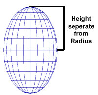
- If the object shape is elliptical in the X or Y plane, enter the appropriate aspect ratio in the X-Y Aspect Ratio text box. The aspect ratio is specified as the ratio of the X radius to the Y radius. If the object is longer in the X direction, the aspect ratio will be > 1. If the object is longer in the Y direction than in the X, the aspect ratio is < 1.
- For example, to create an elliptical spheroid 10 feet long (diameter in the X direction) and 5 feet wide (diameter in the Y direction), an aspect ratio of 2 would be specified. When the object X radius is prompted for a radius of 5 would be given. The resulting object will be 10 feet long (X radius = 5) and 5 feet wide (Y radius = 2.5). Note: if the Radius = Height radio button was selected, the object’s height would be 10 feet.
|
|
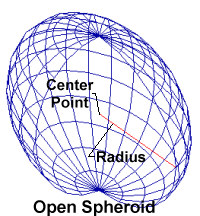
- If an open sphere was created, specify which side of the open sphere is reflective.
- Click OK to return to the graphics window and
locate the center point of the object. Before clicking in the center point,
you will have the opportunity to change the Z coordinate of the center,
if desired. Move the cursor into the Z-Coord
text box
and enter the appropriate value. Then, click the left mouse button at
the object’s center location.
- Note: If the Z-Coord value is not equal to zero,a warning icon will be displayed to alert the user to this condition.
- Drag the cursor to specify the radius of the object and left click again. Alternately, you may specify the radius length from the keyboard.
- Specify the object’s ending angle with the left mouse button. This angle determines the circular segment to create. Whole spheres are created by entering an ending angle that corresponds to the original radius endpoint. Segmented spheres are created by dragging the cursor to indicate its horizontal cross section.