
Round/Elliptical Objects - Vertical Rotation
|
|
|

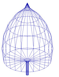
Vertical Rotation objects are created by specifying the circular or semi-circular object footprint in Plan View and the Object Profile in Elevation view. When creating the profile, the bottom and sides are already created for you; you need only specify the shape of the object top. The Object Top cannot dip below the Object Sides, so in some cases it may be desirable to specify the height of the sides as less than the actual height, to allow for some leeway when specifying the top. To create a column with protrusions at the top and bottom, specify the height of the object sides as some small distance (e.g. 0.05 ft), then create the column profile.
Before the object is created, its properties are specified in the Object - Round/Elliptical - Vertical Rotation dialog. These properties include a unique object label, description, wireframe color, labeling options, side height, and surface reflectances. When the object is initially specified, the top, sides and bottom are assigned the same reflectances. You may edit the object, after creation, to assign a different reflectance (color) to each surface individually, if desired.
- From the Add
menu select Object - Round/Elliptical - Vertical
Rotation, or from the Rooms/Objects Toolkit click the arrow adjacent
to the Object - Round/Elliptical button
 . The secondary menu
will appear. Select Vertical Rotation.
. The secondary menu
will appear. Select Vertical Rotation. - Specify a unique label for the object up to 32 characters long. The default label will be Object_1. Unless changed, subsequent labels will be Object_2, Object_3, etc. If a number is used for the label, subsequent labels will be incremented accordingly.
- If desired, a description may be entered, up to 80 characters long. Meaningful descriptions including size and color will be useful for schedules.
- The object will be created in AGi32 using the selected Wire Frame Color. This color is not used in AGi32's Render mode, it is only used to represent the object's shape in the graphics window. By default, this color is blue. To change it, click in the color cell. The Color dialog will appear for your use.
- If surface labeling is desired, click on the Labeling button. A separate dialog will appear for specification of text labels for the object and/or its surfaces.
- Enter the height of the object sides in the Height of Sides text box.
- All object surfaces are assigned a color.By default, the surfaces are assigned a shade of gray corresponding to a reflectance value of 0.5. You may change the reflectance of a surface by simply typing a new value in the Reflectance cell for the Top, Sides, or Bottom. You may change surface color and its corresponding reflectance by clicking in the Color cell for the Top, Sides or Bottom.The Color Selection dialog will appear allowing you to select surface colors based on user defined reflectances. To quickly assign the selected attributes to all surfaces, click on the Surfaces Same Attributes button.
- You may assign a texture to the surface by clicking in the Texture cell. The Select Texture dialog will appear so that you may choose a texture from the Textures database. Alternately, you may browse for a texture anywhere on your system or assign a texture already in use on another surface in the job file. Once the desired texture is selected, you'll determine how the texture should be applied to the surface. Textures may be stretched across the entire surface, applied in a grid pattern or assigned a Static size (representing real dimensions) and tiled on the surface accordingly. In addition, you may opt to rotate the texture on the surface.
To delete a texture from the surface, Ctrl-click in the Texture cell and select the Delete key on your keyboard. When a texture is deleted from a surface, its correlated color and reflectance are used as the current color and reflectance.
- To apply additional surface properties (such as Texture, Transmittance, Transparency, Luminance, Specularity, Color Bleed control or surface specific Mesh Levels) to any of the object surfaces, you must first position the object in the environment. Then, either Edit the object and select the Surface Edit button in the Edit dialog or use the Edit Surface command to select the object.
- Removing Surfaces - Removing surfaces allows you to append other surfaces to factory defined shapes and create more complex models. Surfaces may only be removed from an object after it has been initially located in the environment. Surfaces may be removed by Editing the object and selecting the Surface Edit button in the Edit dialog or using the Edit Surface command once it has been placed.
- The Surfaces Same Attributes button will cause all surfaces to take on the color/reflectance/texture of the first surface in the list.
- Click OK to return to the graphics window and
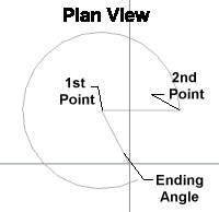
locate the first point of the object. Click the left mouse button. Before
clicking the first point, you will have the opportunity to change the
Z coordinate of the base, if desired. Move the cursor into the Z-Coord text box
and enter the appropriate value. Then, click the left mouse button to
locate the center point of the object base.
- Note: If the Z-Coord value is not equal to zero,a warning icon will be displayed to alert the user to this condition.
- Drag the cursor to specify the object’s radius and left click again. These two points define the object baseline. Alternatively, you may enter the object radius from the keyboard.
|
|
|
|
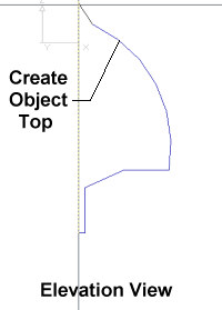
- When you have completed creating the top, click on the right mouse button to close the object and create the surfaces. You will be returned to Plan view.
Note: When specifying the profile in a non orthogonal Elevation view, the snap is changed to .01 and is locked at that value. This small snap setting ensures that the object surfaces will be created correctly.