
The Display Properties dialog Display Properties sets the display parameters for all views in Render Mode. These parameters are divided into Analysis, Model Mode Overlay Settings and Color Temperature tabs.
From the View
menu select Display Properties,
or from the Common toolbar select ![]() .
.
Analysis Tab
The Analysis tab provides display and scaling options.
|
Setting Type |
Default Value |
Description |
|---|---|---|
|
Analysis |
||
|
Display |
Radiosity |
Wireframe - This format is the default selection when Render Mode is first initialized unless the calculations have been already performed. This format shows the environment wireframe and does not consider lighting effects. Hidden Wireframe - This format displays the environment wireframe using the surface visibility properties. If the surface is invisible in the current view (e.g., single sided) it will not show this wireframe display. This display type does not display lighting effects. Shaded - This format displays the environment using the selected surface colors. Lighting effects are not considered.
Radiosity - This format displays the calculated Radiosity solution. It is only available after calculations have been performed. Radiosity Wireframe - This format displays the environment wireframe using the surface visibility properties like the hidden wireframe format. The results must first be calculated, and the wireframe is displayed using the current color format - RGB Color, Grayscale or Pseudocolor. |
|
Color/Metric |
RGB Color (Luminance Only) |
RGB Color (Luminance Only) - This option is only meaningful when Radiosity or Radiosity Wirefram display types are selected (above). Only the Luminance option is available for RGB color.
Grayscale - This option is only meaningful when the Radiosity or Radiosity Wireframe formats are selected. All surface colors are replaced with a corresponding shade of gray thereby producing a grayscale effect. Grayscale can be seen in terms of Luminance or Illuminance.
Pseudocolor - This option is only meaningful when the Radiosity or Radiosity Wireframe formats are selected. Pseudocolor can be seen in terms of Luminance or Illuminance. Each luminance or illuminance value is assigned a unique color value ranging from blue (minimum value) through cyan, green and yellow to red (maximum value). This color type allows an alternative way to view the luminance or illuminance distribution in the environment easily. NOTE: Scales are only available when Exposure=0. |
|
Luminance |
This setting determines whether the luminances or illuminances of the surfaces are shown when the Radiosity or Radiosity Wireframe display formats are selected. Luminance is shown by default and is available for all display color types (selected in the Color section). Illuminance may be applied when either Grayscale or Pseudo Color is selected in the Color section. (If the Color selection is RGB, selecting Illuminance will have no effect; the display will still be Luminance.)
Luminance – This option displays the density of luminous flux projected in a given direction off of the surfaces. In AGi32, all surfaces are considered to be perfectly diffuse, and the luminance on the surface is the same, regardless of viewing direction.
Illuminance – This option displays the density of the luminous flux incident on the surfaces. Illuminance is calculated using the luminance and reflectance of the surface. |
|
|
Light Component |
Direct/Indirect |
This setting allows the user to select which light component is displayed. Direct/Indirect is displayed by default. Direct/Indirect - This option displays both the direct component and the interreflected component of illumination for the rendered environment. Direct Only - Selecting this option removes the interreflected component of illumination from the rendered environment, leaving only the direct component visible. This selection provides a good visual indicator of the efficiency of electric lighting and daylighting to effectively illuminate surfaces directly. Indirect Only - Selecting this option removes the direct component of illumination from the rendered environment, leaving only the interreflected component visible. This selection provides a good visual indicator of the efficiency of interreflected light and effectiveness of surface geometry and reflectance, especially for daylighting analysis. |
|
Options |
||
|
Textures |
Setting disabled by default |
Selecting this option toggles textures on in Shaded and Radiosity Views. Toggling Textures is also available from the Status Bar. |
|
Wireframe Overlay |
Setting disabled by default |
Selecting this option allows you to overlay the wireframe on top of RGB, Pseudocolor or Grayscale color displays, to see the underlying element mesh. Wireframe Overlay is also available from the Status Bar. |
| Colorize Patch/Element Wireframe | Setting enabled by default | When the wireframe is displayed and this option is selected, Patches are outlined in blue, Elements in red. |
|
Luminous Box Overlay |
Not enabled |
Selecting this option displays the luminous box for each luminaire along with the aiming axis. |
| Transition Surface Vectors | Not enabled | Selecting this option displays the vectors showing the "direction" of the transition surfaces, e.g., Daylight Transition Glass - Transparent. The vectors must point into a space to allow daylight in. |
|
RGB, Grayscale and Pseudo Color Scaling |
||
|
Scaling |
Off
|
Apply Linear or Power Law scaling for luminance or illuminance mapping in the rendered environment. (RGB scaling can only be applied to luminance display.) See below for more information. |
|
Scale Size |
Auto
|
Sets the size of the Scale to the left of the image. See Scaling section below this table for more information. |
|
Exposure |
||
|
Set Exposure For |
All Surface Types |
Interior surfaces will typically be much less bright than exterior surfaces receiving daylight. AGi32 provides three exposure options, to handle these three categories: All Surfaces Types (default), the interior (Non-Daylight Surfaces) and exterior (Daylight Surfaces).
All Surface Types - In this setting, the appearance of the exterior and interior environments are set separately, enabling both to look appropriate in the same image. (Your camera couldn't do this!). The All Surface Types setting works for most environments. If the average reflectance of the current environment differs greatly from the assumed 18% value (see Concepts tab, top of page, for more info), the image may appear under- or overexposed. Exposure modification may need to be applied to properly display the image.
Non-Daylight Surfaces - This setting causes the exposure to be appropriate for the less-bright interior surfaces, leaving the daylight surfaces to look over-exposed. This option may be useful in environments where both non-daylight and daylight surfaces are present and daylight is NOT enabled, or where daylight is enabled but the exterior overexposure is not important.
Daylight Surfaces - This setting causes the exposure to be appropriate for the brighter, exterior surfaces, leaving the interior surfaces to look comparatively dim, or underexposed. This option may be useful in environments where both non-daylight and daylight surfaces are present, daylight is enabled, and the appearance of the exterior is more important than that of the interior. |
|
Exposure Setting Note: Exposure Setting may also be adjusted from the Render Toolkit. |
0 |
This parameter allows you to override the automatic exposure setting set by AGi32 based on average scene luminance. You may increase the screen luminance by increasing the Exposure value and therefore make the image ‘brighter’ on the screen. However, changing the Exposure and increasing the visual brightness of the environment on the screen does not actually change the calculated luminance values. This allows you to add detail to shadows or decrease the overall scene brightness without affecting the actual luminance values or the integrity of the calculated point-by-point values. The Exposure values may be set from –8 (minimal brightness) to 8 (maximum brightness) in increments of 0.25. Click on Concepts tab (top of page) for a table of exposures and equivalent reflectances. Note: When applying a maximum luminance or illuminance value (see Scaling above), the Exposure setting must be set to 0. |
Scaling
This section allows you to display a graphic luminance or illuminance scale for the rendered environment using the range of values between minimum and maximum. You may also specify a constant maximum luminance or illuminance value for Grayscale or PseudoColor environments, or a maximum luminance value for RGB environments, allowing you to compare environments side by side. Once enabled, all surface luminances (or illuminances) will be scaled according to the specified value. The value specified should be appropriate for the type of environment considered (i.e., exterior vs. interior, commercial vs. industrial, etc.). The Exposure setting must be set to zero to use Pseudocolor scaling.
For example, in a site lighting environment, a maximum illuminance value of 300 footcandles is calculated. This unusually high level of illuminance may occur directly below the luminaire on the pole surface itself (it is an object in AGi32 and therefore can receive light), whereas the remainder of the site exhibits illuminance of 10 footcandles or less. The range of values is so large in this case, you may only see a hot spot directly on the poles, with the site itself appearing very dim. By scaling the maximum illuminance to 10 footcandles, which may be the maximum on the pavement, all illuminance values of 10 or higher are mapped to the red range. The remainder of the site will then exhibit a more legible gradient.
The maximum luminance and illuminance calculated for each environment are displayed in the Render Display Properties dialog. Using these values as a guide, you can select an appropriate maximum luminance or illuminance value to use. When enabling this option, the exposure must be set to zero.
Luminance - The maximum reflected luminance for the environment as well as the maximum emitted luminance are displayed in Candelas/Square Meter, regardless of the current units, for Non-Daylight and Daylight surfaces. The Max Emitted refers to the luminance emitted from self-emitting surfaces (specified as having non-zero Luminance in the Surface Edit command). If no self luminous surfaces are present in the environment, the Max Emitted luminance value will be zero.
By clicking the Apply Maximum (Luminance) selection box, you may display a luminance scale to the left of the image. An alternate maximum may be entered to scale the environmental luminances, if desired.
Note :By default, the Apply Maximum setting will be set to the largest luminance value (reflected - non-daylight, reflected - daylight, emitted - non-daylight, emitted - daylight)
Illuminance - The maximum illuminance for the environment is displayed in Footcandles or Lux, based on the current unit type specified in System Settings. By clicking the Apply Maximum (Illuminance) selection box, you may display an illuminance scale to the left of the image. The Apply Maximum selection box is only available when Grayscale or Pseudocolor is chosen for the Radiosity display type. An alternate maximum may be entered to scale the environmental illuminances, if desired.
Note :By default, the Apply Maximum setting will be set to the largest maximum illuminance value non-daylight or daylight)
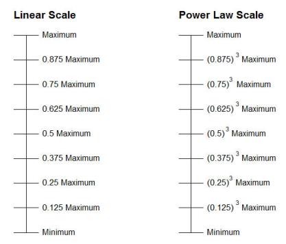
Scale Type - This option allows you to choose a Linear or Power Law scale to apply to the rendered environment. A linear scale displays the values in the range in equal increments. For example, in a linear luminance scale with a minimum/maximum range of 0 to 20, one quarter up from the minimum would be 5, the midpoint would be 10, three quarters up would be 15, etc.
A power law scale is useful when there is a wide range of values displayed in the rendered environment (luminance or illuminance) and the values within the lower end of the range need to be displayed in detail. Power law expands the lower range of the scale, yielding more detail (the smaller values are spread over a larger range on the scale). This type of scaling is especially useful when there are a few surfaces in the environment with very high luminances and the remainder contain much lower values (e.g., indirect lighting interiors and site lighting with poles).
Note that for RGB displays, only luminance can be scaled, by applying a Maximum Luminance value, but the actual scale is meaningless with RGB and therefore is not displayed when applying a maximum luminance to an RGB display.
Display Scale With Image - This option applies a graphical luminance or illuminance scale on the upper-left side of the graphics window. A scale may only be displayed when the Apply Maximum selection box is checked. The scale may be applied whether the Maximum value is scaled or not. The scale becomes part of the image and is shown when printing or exporting, and is saved for use in Imageports in Reports.
Scale Size - Scale size is selectable. The default selection is Auto.
- Auto: Scale Size (small, medium or large) is automatically determined based on image height:
- If height < 600 pixels, Small scale is displayed
- If height ≥ 600 and ≤ 1200 pixels, Medium scale is displayed.
- If height > 1200 pixels, Large scale is displayed.
- Small: 365 x 82 pixels. Suitable for any image size.
- Medium: 594 x 110 pixels. Suitable for any image size where height ≥ 600 pixels.
- Large: 780 x 155 pixels. Suitable for any image size where height > 800 pixels.
- If you select Medium or Large but the Scale is too tall for the display, it will be downsized automatically to prevent it from being cut off.
Model Mode Overlay Settings Tab
The Status Bar provides the command Toggle Model Overlay. This command overlays all Model mode entities on top of the current rendered environment (e.g., drawing entities, calculation points, Isolines, photometric webs, luminaire templates, etc.).
Model Mode Overlay is WYSIWYG. All entities are displayed. The Display Properties - Model Mode Overlay Settings tab provides visibility control for all related entities. By default, all entities are selected. To hide entities (e.g., to simplify image or speed up display interaction), de-select them in this tab.
The Model Mode Overlay may also be toggled on and off entirely from this tab (Check or Uncheck Model Mode Overlay selection box at top of tab).
Text Display
Overlaid text can be displayed using two methodologies: Outlined (Fast) and Filled. The default method is Outlined (Fast), which is recommended for everyday use.
- Outlined (Fast) – Text is displayed as an outline and is visible when viewed from behind (e.g., back side of wall).Outlined text is much less graphic intensive and has less effect on display speed and interactive movement in Render mode.
- Filled -- Filled Text behaves similarly to single-sided surfaces; it is not visible from the back side of the text. For example: If you have calculation points on a wall, the calculated values (text) will not be visible when view from the back side of the wall (in Model mode the text appears upside down when viewed from the back side).
- Filled Text is more graphic intensive and may slow display speed and interactive movement in Render mode. Increasing Hardware Acceleration (set using Windows Control Panel - Display) may eliminate or alleviate this issue. Please be aware that Hardware Acceleration has been known to cause a multitude of display issues if the display driver is out of date or buggy.
- Filled Text may be useful for presentation purposes (e.g., image capture, movies, etc.).
Technical Details
- Model Mode Overlay is currently not available for ray traced images (e.g., ray trace image, daylight study – ray trace images, movie – ray trace images).
- In order to display text, AGi32 creates font styles for each unique combination of font (font name) and font properties (bold, italic, underline and strike-through). Creating font styles can have a significant effect on performance. Therefore, it is recommended to minimize the use of different fonts and font properties in Model mode when including text in the overlay.
- The extents of the display in Render mode may change when the overlay is toggled on and off. To reestablish the view and center the display, simply select one of the Default Views.
- The Model Overlay is recreated each time Render mode is displayed and/or whenever the View Properties in Render mode are changed (e.g., adding additional views with View Manager). If you experience significant delays when the overlay is enabled, you may want to consider removing some entities from the overlay list.
- Model Mode Overlay entities do not interact with the environment and are not considered in the calculations.
This tab allows you to set the Correlated Color Temperature (CCT) to use as the basis for rendering the environment. This is used in conjunction with Source Color to produce more realistic renderings. Without adjustment, all colors are rendered with 6500K as the "white point." This would make metal halide (approx. 4000K) appear rather warm.
The Current CCT is the environmental CCT that is currently employed in the model.
By default, Automatic is selected, meaning that AGi32 will automatically adjust the environment CCT to account for human chromatic adaptation. The adjustment is based on the CCT of the light source used in the model; this is the environment CCT. If there is more than one source, it uses the highest source CCT. For more information on chromatic adaptation and the adjustment that AGi32 makes, as well as example images showing the concepts applied, click on the Concepts tab at the top of this topic.
Important: The accuracy of the Automatic adjustment is highest for sources with a high CRI (70 or higher). The lower the CRI, the more difficult it becomes to predict the chromatic adaptation color shifts as the color temperature is changed.
The Automatic adjustment is a subjective estimate only. The user is able to manually adjust the environment CCT if the effect achieved is "not quite right." A different environment CCT may be set by selecting Set CCT and then entering a correlated color temperature value (allowable range: 2000K to 25000K). Click the OK or Preview button to implement the change.