
Photometric File and Luminous Box
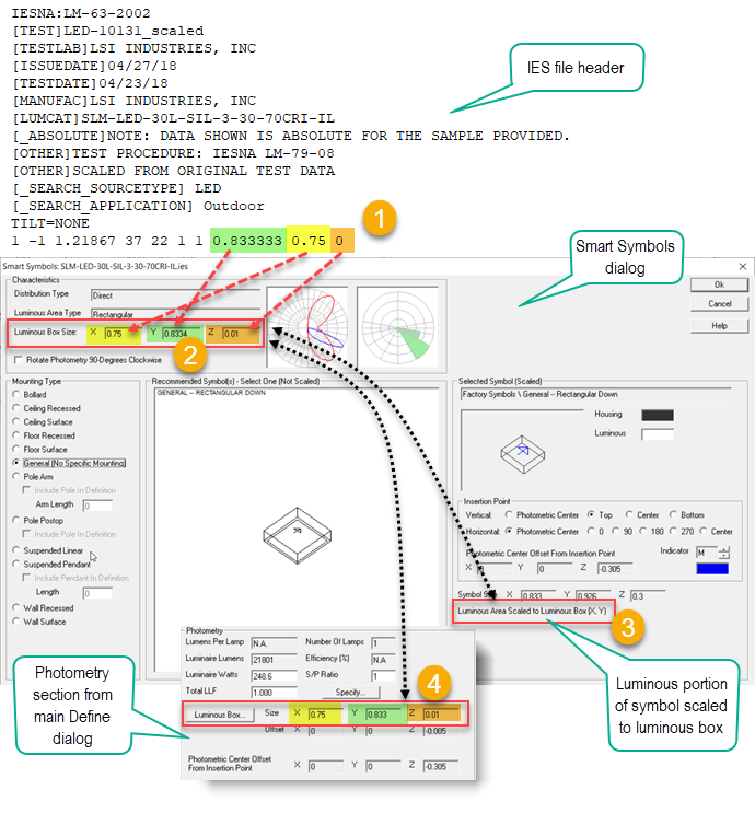
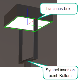
The Luminous Box is defined by the luminous area defined in the photometric file. The center of the Luminous Box corresponds with the "Photometric Center" of the luminaire, the point from which all calculations are referenced.
The dimensions of the luminous area are obtained from the photometric file. This information should be accurately reported by the laboratory responsible for the photometric report. If it is not accurate you may find your symbols are scaled incorrectly and Full Radiosity calculations may be less accurate.
The example below presents the luminous dimension data in context of an IES file. EULUMDAT and CIBSE file formats are slightly different but the end result is the same.
- In the IES file, the last three values in the line following TILT=NONE correspond to the luminous area dimensions as Width, Length, Height. Where:
- Width is the distance across the luminous opening in the 90-270 degree photometric plane (stated as perpendicular to 0 in IES LM-63). This is Y.
- Length is the distance across the luminous opening in the 0-180 degree photometric plane (stated as parallel to 0 in IES LM-63). This is X.
- Height is the height of the luminous surface (not the height of the luminaire).
-
The X, Y and Z luminous area dimensions from the photometric file are displayed in Smart Symbols dialog.
-
If the luminous Z is zero, AGi32 will add a small negative distance to allow the luminous bottom of the symbol to be below the insertion point. This prevents the luminous surface from being coplanar with a ceiling surface and avoids subsequent Z-buffering issues in Render mode. This is shown as "Photometric Center Offset" in the Z-direction in the Symbols dialog. It is shown as having a very small thickness in Smart Symbols (0.01) to separate it from the symbol housing.
-
-
The Luminous Box is used to scale the luminous area of the symbol selected as default behavior. This can be changed in the symbols dialog.
-
The Luminous Box dimensions are transferred to the Photometry Section of the Define dialog. Adjustments to the Luminous Box including optional Offset can be performed by clicking the Luminous Box button.
In the IES file, the value immediately proceeding the three numbers for Width, Length, Height indicates the units of measure (1=Imperial, 2=Metric). Dimensions are ALWAYS in decimal feet or meters per IES LM-63 and not in inches or millimeters.
Example
Clicking on the Luminous Box button in the Define dialog (#4 above) opens the subset of the Symbols dialog shown below. This shows the Luminous Box and indicates how the symbol's luminous area is auto-scaled to the size of the Luminous Box.
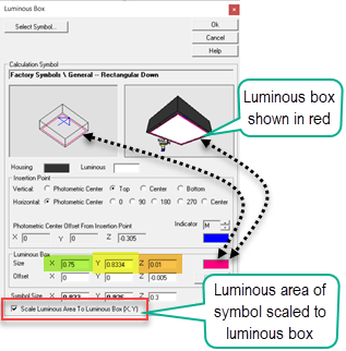
To reiterate: the luminous box is circumscribed using the luminous area data from the photometric file. The X-dimension corresponds to the distance across the luminous opening along the 0-180 photometric plane. The Y-dimension corresponds to the distance across the luminous opening along the 90-270 photometric plane. The Z-dimension is the luminous height and not the height of the luminaire housing.
Visualizing the Luminous Box
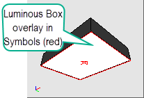
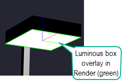
The Luminous Box dimensions can be seen in the symbols dialog and viewed in Render Mode by enabling the Luminous Box Overlay from Render - Display Properties. This can be very handy for trouble shooting should the dimensions be incorrect in the photometric file.
|
|
| As visible in the symbols dialog | As visible in Render Mode |
Calculation Implications
AGi32 uses the dimensions of the luminous box when performing lighting calculations using Full Radiosity Calculation mode in order to consider the area nature of the source. If the luminous dimensions found in the photometric file are incorrect, the lighting calculations may not be accurate. For example, if the distribution of a 1x4 luminaire is emitted from a point source instead of an appropriately sized luminous area, the luminous area will not be discretized appropriately to accurately compute light on nearby surfaces. The effect is most pronounced when the luminaire is very close to a surface. In Direct Calculation mode, the luminaire is assumed to be a point source.
Care should be taken that the luminous box does not extend outside of a room and is not truncated by any objects. The luminous height (Z) should not be above the ceiling. If the photometric file has luminous height, the luminaire should be mounted below the ceiling at a distance equal to, at least, that dimension. This is typically handled when the Vertical insertion Point of the symbol is specified as Top. AGi32 's default insertion points are based on Mounting Type in the Smart Symbols dialog and can be modified in the Symbol dialog if necessary.
Luminous Box and Calculation Symbol Luminous Area
The luminous box is aligned with the luminous area in the Calculation symbol by default. It can be manually "Offset" in the symbols dialog if desired (unusual). Specifically, the Z=0 portion of the luminous box is aligned with the center of the luminous area of the Calculation symbol. This association may place the luminous box at some distance away from the insertion point of the luminaire which corresponds to the luminaire mounting height. As an example, if the Shoebox-Yoke symbol is selected, the luminous area is located 1 foot above the insertion point of the luminaire due to the size of the symbol. If a 15 foot mounting height is specified, the calculations will actually consider the luminous source at 16 feet above grade. The Z-height of the symbol yoke can be scaled to shorten that distance.
See also the topic Luminaire Application.