
The location of the Photometric Center in AGi32 is based on a set of variables associated with the selected symbol, luminous box size and offset. This is a detailed topic and is worthy of some examples below. It is also important that users understand the material presented in the following topic links.
Luminaire Symbols (Procedures tab from above)
File Compatibility (Knowledgebase link)
Full Radiosity Method
The Full Radiosity Method considers the luminaire size and location accurately in the Radiosity calculations. First, the luminous area is extracted from the photometric file and inscribed within a luminous box. The luminous box is intended to represent the luminous area of the fixture. If the luminous box is larger than 1 square foot, it is subdivided along the largest axis and the lighting distribution is divided equally among these pieces if necessary. The piece size is specified Luminaire Subdivision in Advanced System Settings, and is 1 foot by default. This process allows the light “energy” to emit across the entire luminaire (as happens in real life) as opposed to being emitted entirely from the center (as a point source).
The luminous box is located within the selected Calculation symbol according to the luminous areas ascribed to the symbol. Calculation symbols with a luminous surface located at the bottom of the symbol will have the luminous box centered at the bottom of the symbol. Calculation symbols with a luminous surface located at the top of the symbol will have the luminous box centered at the top of the symbol. Calculation symbols with a luminous surface located at the top and bottom of the symbol or along the sides will have the luminous box centered within the symbol.
In addition, the symbol itself is attached to the cursor using the insertion point of the symbol which can vary depending on the symbol and mounting type selected (with optional Arm's and Offset's). Please refer to the Symbols topic. The Mounting Height of the luminaire correlates to this insertion point. If the insertion point of the symbol is not located in the same plane as the luminous area, the light “energy” is emitted from a different location than the specified Mounting Height. Examples of this are discussed below:
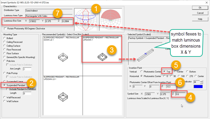
Interior application
- An Indirect/Direct photometric file is selected.
- The Suspended Pendant Mounting Type is selected in Smart Symbols.
- From the symbol choices we select something with a luminous top and bottom (updown) to represent the luminaire.
- The default height of this symbol is 0.6 feet.
- Its default insertion point is Top (based on mounting type selected).
- Recall, that a symbol with luminous areas on the top and bottom will locate the luminous box at the center of the symbol. Looking at the symbol height from #4 we can understand the Photometric Center Offset of 1/2 that amount, or -0.3 to locate it in the center of the symbol. If a Mounting Height of 8’ is specified (to the symbol insertion point), the luminous box is actually located at 8 - 0.3 = 7.7’. The luminous flux is emitted from 7.7'.
- Looking at the Luminous Box Z-dimension of 0.2084, we realize the symbol height is a little large at 0.6'. The software automatically flexes the X and Y dimension of the symbol to match the luminous box (#3). It does NOT automatically flex the Z-dimension, this may not be desirable in some cases. You can change the height of the symbol to match the luminous box if you like from the symbols dialog (not Smart Symbols shown here). This would reduce the difference between the mounting height and photometric center described in #6 to half of 0.2084, or 0.1042.
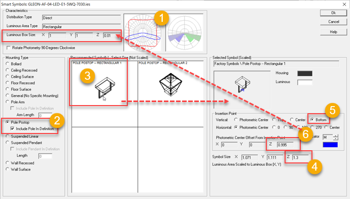
Exterior application
- A Type V Area Lighting photometric file is selected.
- The Pole Postop Mounting Type is selected in Smart Symbols.
- The Shoebox Yoke symbol is chosen to represent the luminaire. It is automatically sized in X & Y to match the luminous box dimensions (the symbol has a small border around the luminous area so it is slightly larger).
- The default Height (Z dimension) of this symbol is 1.3 feet.
- Its default insertion point is Bottom (bottom of the yoke).
- The luminous area is located at the bottom of the housing (with no discernible Z-dimension). Based on symbol dimensions, this is computed to be 0.995' above the insertion point at the yoke.
- If a Mounting Height of 25’ is specified, the luminous box is actually located at 25.995’ (or roughly 26'). Your calculation points would pick up the luminous flux emitted from 26’.
Behavior of Poles and Pendants
Poles and pendants are physical objects in Full Radiosity Method. Each pole has a rectangular footprint 4" on each side, Pendants are 0.6" square. If selected, they acquire the housing color of the associated luminaire. Poles and pendants block and reflect light and should be selected such that they do not block the luminaire's luminous area. When selecting a pole, use Arm Length to distance the pole from the luminous box. If a pole is needed directly beneath the luminaire, be sure to select an appropriate symbol such as "Shoebox with Yoke".
Pendants are best applied to direct distribution luminaires (like a Hibay). When used with an indirect light distribution, the pendant may block the luminous box unless an appropriate offset is used. See Luminous Box.
Even if you do not view the rendering, the Calculation symbol is a physical object used in the calculations. It is important to select an accurate symbol to physically represent the luminaire size. In Full Radiosity Method, the luminaire housing obstructs and reflects light in the environment, making its physical shape and size a potentially significant component in the calculations. AGi32 considers the effect of luminaires in the calculations, as would occur in real life. To compare AGi32 to other lighting software that does not consider the effects of luminaires in the calculations, choose the NULL symbol for the Calculation symbol. This removes the physical luminaire presence from the calculations. In addition, the NULL symbol places the luminous box at the insertion point.
The selection of an appropriate Calculation symbol is also important for accurate placement of the luminous box, as illustrated above.
Direct Only Method
Direct Only Method considers the luminaire to be a point source regardless of the luminous area specified in the photometric file. Luminaire Photometric Center position is the same in Full Radiosity Method and Direct Only Method (AGi32 version 20 and forward)..
In the Direct Only Method, the luminaire symbols, poles and pendants are not considered as objects in the calculations. Any Rooms and Objects present are considered as obstructions (will block light), but they will not reflect light.