
![]()
Luminaire Symbols - Concepts
AGi32 includes an extensive luminaire symbol library to assist you in individualizing your luminaire definitions. AGi32 also provides many generic symbol representations that will "flex" to match the size of the luminaire's Luminous Box. As an example: a simple square box can flex to become a long narrow shape. This flexing occurs automatically in the Smart Symbols dialog when first selecting a photometric file.
A luminaire definition has two symbol references, a Calculation symbol and a Drawing symbol. Calculation symbols are used for calculation purposes and are seen in Render Mode. They are physical objects. Calculation Symbols participate in the calculations in the Full Radiosity Method by reflecting and occluding light within the environment. They are constructed of two basic surface types: the symbol's housing and its luminous surface. Symbol housing colors can be adjusted to your liking corresponding to a particular reflectance. Luminous Color (luminous area) is white by default but can change based on any change in luminous color (Source color, filters etc.). The luminous area of the symbol is flexed to match the luminous are from the photometric file (the Luminous Box).
Drawing symbols are symbolic line drawing representations of the luminaire in Model Mode. Drawing symbols do not participate in the calculations in any way, they are simple line drawings. These symbols represent the luminaires in Model Mode and when printing or exporting the job file as a CAD file. As default software behavior the Drawing symbol is a line drawing of the Calculation symbol (used in Render Mode). They can be selected individually by selecting the check box in the Drawing Symbol area (Symbols dialog) titled "Different Drawing Symbol".
Use the numbered reference below to help understand the symbol selection process and associated variables.

1 - Opening the Symbols dialog
From the main Define dialog click on either graphic for Calculation or Drawing Symbol to open the Symbols dialog. The initial luminaire symbol assignment takes place in the Smart Symbols dialog when selecting a photometric file. Enter the Symbols dialog if you would like to make a change from that initial assignment. By default the Calculation and Drawing symbols are linked, the Drawing symbol is a line drawing representation of the Calculation symbol which is composed of object geometry.
At the top of the Symbols dialog you will find the Selection Options used to filter the symbols database and provide relevant choices. Symbols are stored in folders found in C:\ProgramData\AGi32\LuminaireSymbols*. You can filter the folder list if you like using the menu but this is usually not necessary as the default is All Folders except Legacy. It is typically more useful to filter by Category which relates to application and Mounting Type. The Search field is also a fast way to get where you want to be. For more details on this section click the Procedures link at the top of this page.
* If you are coming from a previous version of AGi32 any former symbols folders you might have created are migrated to this new location and will appear in the menu.
3 - Calculation Symbols and Insertion Point
Calculation symbols (formerly render Mode symbols), represent the appearance of the luminaire in Render Mode and play an important part in the location of the luminous area from the photometric file. Calculation symbols are physical objects and participate in the radiosity solution computed in Full Calculation mode. This means they can cast shadows and block reflected light (just like the real world) so in many applications it is important they are close to true size. You can control the Housing color (see #7 below) and Luminous color (see #8 below) of the Calculation symbol should you want to change from default values.
The Insertion Point is the point on the symbol that will be attached to the cursor when luminaires are placed in Model Mode unless they are using an Arm Length. In this case the Arm will attach to the symbol insertion point and the cursor in Model mode will place the pole (or the end of the arm). The insertion point corresponds to the Mounting Height value entered in the Luminaire Toolkit (MH). You have the flexibility to move the insertion point on the symbol both vertically and horizontally from the default settings using the adjustments in the dialog. You can see the location of the insertion point on the symbol drawings as a blue arrow. Adjust the arrow's size by changing the Indicator (S, M, L, XL, XXL).
NOTE: Insertion point defaults are intelligent and typically best practice for the luminaire Mounting Type selected using Smart Symbols.
The insertion point DOES NOT always represent the photometric center of the photometric file and depending on mounting selected may be some distance away. The photometric center will be the center of the Luminous Box.
See also the topic Luminaire Application.
Vertical Insertion Points
Photometric Center - This is the center of the Luminous Box.
Top - This is the top of the symbol housing. it is most useful for ceiling surface mounting.
Center - This is the center of the symbol housing.
Bottom - This is the bottom of the symbol housing and is most useful for recessed mounting. The luminous box is automatically offset slightly below the housing to ensure it is below the ceiling plane.
| Top | Center | Bottom |

|
||
Horizontal Insertion Points
Photometric Center - This is the center of the Luminous Box.
Angular entries follow the global coordinates system used by AGi32 for Orient angle. 0 East, 90 North, 180 West, 270 South. The luminaire's zero degree horizontal plane of photometry faces East. (See images below)
0 (degrees) - East side of the luminaire
90 - North side
180 - West side
270 - South side
Center - This is the horizontal center of the luminaire symbol housing. It may include a yoke or other geometry and does not necessarily coincide with the luminous center.
| Photometric | 0 degrees | 90 degrees | 180 degrees | 270 degrees | Center |

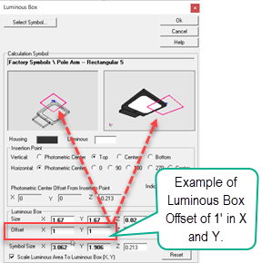
4 - Luminous Box and Offset
The Luminous Box dimensions are extracted from the luminous dimensions of the photometric file. Testing laboratories are generally careful to be accurate with this information. The luminous dimensions are X,Y,Z dimensions of the luminous portion of the luminaire. They are not the overall dimensions of the luminaire. If necessary, you can correct the dimensions of the luminous box in the Symbols dialog or the Luminous Box sub-dialog (a small portion of Symbols dialog available from the Luminous Box button in main Define dialog). Generally, incorrect dimensions will be easy to notice as the symbol size will be distorted from what you are expecting due to the automatic scaling of the luminous portion of the symbol to the Luminous Box.
The Luminous Box can be offset from the symbol if desired. AGi32 automatically builds in a very small offset for the Z-dimension to cure common interference issues with ceiling planes. An obviously non-practical example of Luminous Box Offset is shown in the capture below.
Let's look at a more practical possibility. Imagine a wall mounted luminaire. Radiosity technology does not render sources very close to surfaces with high accuracy. This can be due to meshing inadequacies and source descritization. As a result you will often see an unrealistic light pattern very close to the luminaire. You can offset the luminous box away from the wall slightly without dramatically affecting calculated results and end up with a dramatic improvement in rendered images.

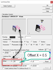
5 - Symbol Size and Scale Luminous Area
The Symbol Size is the physical extents of the objects used to create the symbol. The luminous area is some subset of the symbol size depending on what sort of luminaire it is representing. In the case of the wallpack luminaire in #4 above the luminous area is roughly the lower half of the luminaire. Agi32 will automatically scale the luminous area of the symbol to the dimensions of the luminous box from the photometric file. This allows the symbol to be true scale.
Symbols are simple representations of luminaires and may not truly represent the products you are using. You can scale any symbol manually in three dimensions to more closely approximate your intended product. However, be aware of the resizing that occurs when the checkbox described below is selected.
Scale Luminous Area to Luminous Box (X,Y) - This checkbox will be enabled by default with factory symbol selections. Custom symbols coming from the Instabase will not have this box selected to avoid resizing (they are usually created true size). When selected the luminous portion of the symbol (area seen as white) will be scaled to match the physical luminous box dimensions from the photometric file. If the luminous dimensions found in the photometric file are incorrect you will typically notice an undesirable resizing of the symbol.
6 - Different Drawing Symbol
By default, the Drawing Symbol is a line drawing replica of the Calculation symbol. You can decouple these symbols by selecting the check box in the Drawing Symbol section titled "Different Drawing Symbol". This is intended to allow you to use a 2-dimensional line drawing that might match a CAD drawing. There is a collection of these symbol types listed in the Drawing Category (symbols selection). You can also easily add your own using the AGi32 command to Create a Drawing Symbol. See also "Decoupling... in the Procedures topic linked above.
The default line width of factory supplied symbols is 1 pixel. A Pixel is the smallest available line thickness. When placing luminaires on a complex background or printing in black and white, the symbols may be more distinguishable if the line width is increased. Line widths other than Pixel are stated in current display units (feet or meters). The line width scrolls in multiples of 0.25, although any value may be manually entered into the text box. If a value of zero is entered, the line width will default back to Pixel.
Drawing symbol color
For a Model mode symbol you can change the Wireframe color by selecting from a common color dialog. If the selected color does not show well with your background color (black for example) then AGi32 may "flip" the color to an opposite (See System Settings/Advanced Flip Color Tolerance).

7 - Housing Color (Calculation Symbols)
The Housing Color is the color of the non-light emitting portion of the symbol. By default all surfaces are 50% gray. To change the color of the symbol housing click in the cell adjacent to the Housing Color label.
Selecting the Housing color is an easy and subjective choice. Simply set the Hue slider then drag your cursor around the Saturation and Luminance box to mix a color. The reflectance of that color is shown under the large swatch on the right side of the dialog. You can type a different reflectance if you prefer, the Saturation and Luminance sliders will adjust to match. Alternatively, you can enter HSL or RGB numbers in the cells provided if that information is available.
You can also save your choices as Favorite Colors using the button.

8 - Luminous Color (Calculation Symbols)
Luminous color is the color of the light emitted from the luminous portion of the symbol. Selecting an alternative Luminous Color allows several options, each of which has different behavior and important implications for your calculations. There are three methods that may be used: Source Color, Color Filters, or Color Mixer.
See SRE Color and SRE Color - Concepts for more detailed information.
Source Color
You can easily select a source CCT if you are interested in visualizing its effect in Render mode. All source CCT's are shown relative to the 6500K white point of the computer display which makes them appear much warmer than your perception. Adjustments are required in Render mode to set the white point of the visualization to recognize an expected effect. See SRE Color.
Setting Source Color does not effect the calculated values. It is entirely for visualization.

Color Filters and Color Mixer
You can assign a color to a light source as a filter (Lee and Rosco examples included) or by simply mixing a color as RGB components. Be aware that changing the color of the luminous area to other than white (100%) by means of the Color Filters or Color Mixing method will derate the output of the luminaire, as would be expected when applying a real filter or gel. This can be useful for approximating the effect of colored gels applied to the light source, as the depreciation is realistic. The Color Temperature setting does not derate the luminaire output. See SRE Color topic for more details.