
![]()
The initial symbol selection is performed using the Smart Symbols dialog when opening a photometric file. Smart Symbols can be disabled in System Settings (not recommended). If Smart Symbols is disabled, all luminaires will come in to the Define dialog using the default Calculation and Drawing symbol selections from System Settings.
Once a photometric definition is available in the Define dialog, symbol changes (different than your selection in Smart Symbols) can be made by clicking in the graphical cells for Calculation or Drawing symbols. This will open the main Symbols dialog as shown below. By default, the Calculation and Drawing symbols are the same. See "Decoupling..." below.
Symbols Organization
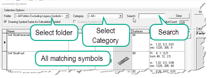
The Symbols collection is organized by Folder and Category with a Search field to narrow the displayed selections. If you know a few characters of the symbol name, searching is very fast (See Search below).
Folders
- All symbols are now stored in the master folder titled LuminaireSymbols. Path: C:\ProgramData\AGi32\LuminaireSymbols.
- The symbols delivered with the software are stored in a folder titled Factory Symbols.
- Symbols from legacy versions of AGi32 are stored in a folder titled Legacy.
- All custom folders you may have created using previous versions of AGi32 have been migrated to LuminaireSymbols and will be visible in the menu.
- The default folder selection is <All Folders Excluding Legacy Symbols>.
Categories
We have organized the symbols into folders by Category (application or mounting). This makes it easy to narrow the number of selections to symbols that make sense before browsing.
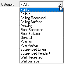
- Select a Category that matches your application:
- Examples:
- Pole mounted luminaires with an Arm should select the Pole Arm category.
- Ceiling recessed luminaires should select Ceiling Recessed.
- Luminaires mounted on a wall surface, select Wall Surface.
The Categories are intuitive making it easy to find symbols suitable for your application.
Search
The Search field can make it easy to find symbols by using just a few characters found in the symbol name. This works even if they exist in your custom folders. Some users will find it easy to enter a few search characters to find familiar symbols without even selecting a Category or Folder. Refining the search to a specific Folder or Category narrows the search even further.
Examples:
- Given defaults in the Folder and Category menus (no selection), enter the characters "rec" (no quotes). This yields recessed and rectangular symbols. Refine the search by entering "rece" and you see only recessed, enter "rect" and you see only rectangular.
- Try entering "wall", this provides all wall symbols, both surface and recessed.
- Enter "cob" and you will see the Cobra Head symbols (street applications).
Select a Symbol
With the collection of symbols narrowed down using the Folder and Category menus and Search function, scroll the mouse wheel to see the available selections. Click anywhere on the symbol display line to make the selection.
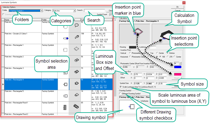
The right side of the Symbols dialog contains a wealth of information. The software is intelligent about the selections here and in many cases you will not need to make modifications.
-
If you have not separated the Drawing symbol from the Calculation symbol (see Decoupling below), the selected symbol will populate both the Calculation and Drawing symbol graphic windows on the right side of the dialog. To select a different Drawing Symbol see Decoupling below.
-
The Symbol Insertion Point will be selected based on the symbol and the Mounting Type selected originally in Smart Symbols. The blue arrows in the two views of the Calculation Symbol will show the location of the insertion point. The Insertion Point is where the AGi32 model cursor will be attached to the symbol which will be located at the mounting height (MH) value entered in the Luminaire toolkit. Insertion points are selected intelligently when using Smart Symbols for various Mounting Types. You are free to select an alternative Insertion Point in both Vertical and Horizontal directions. Experiment with the selections and watch the blue arrow move. NOTE: the Insertion Point is NOT necessarily the location of photometric center. This will be the location of the Luminous Box. The offset of the photometric center from the insertion point is shown. This is typically the distance from the center of the luminous area of the symbol to the selected insertion point.
-
The Luminous Box size and Offset are shown. The Luminous Box is sized according to the luminous dimensions from the photometric file. If this information is not correct in the photometric file, the luminous box will be distorted and can produce inaccurate calculations. The Luminous Box can be Offset if desired although this is not generally necessary. A small Z-dimension offset is included by the software to ensure that the luminous portion of the symbol does not conflict with a ceiling plane.
-
The luminous area of the symbol (white appearance in Render) will automatically be scaled to match the luminous dimensions from the photometric file (the Luminous Box) when the Scale Luminous Area to Luminous Box (X,Y) check box is selected. It is enabled by default. This is very handy as it allows symbols to "flex" to resemble the photometric file selected and portrays the symbol in real-world scale. For example, a simple rectangular symbol will flex to become a narrow linear pendant when the pendant luminous dimensions are applied to the rectangular symbol. Symbol size is shown for reference. You can manually scale the symbol if preferred, this will automatically deselect the Scale Luminous Area... check box. You can scale the Z-dimension without affecting the luminous box and luminous area relationship.
Decoupling Calculation and Drawing Symbols
If you prefer to use a different Drawing symbol than the Calculation symbol line drawing, such as a 2D line drawing used in project planning, follow the steps below:
- Open the main Symbols dialog by clicking in either the Calculation of Drawing symbol graphic cells in the Define dialog.
- In the Drawing Symbol section, check the box titled "Different Drawing Symbol".
- Select a new Drawing symbol from the left side of the dialog.
- If you are interested in 2-dimensional line drawing symbols, a collection can be found in the "Drawing" Category.
- Notice the Drawing symbol section now is highlighted in blue as a reminder.
- You can recouple the Drawing and Calculation Symbols by removing the check box. The Drawing symbol will revert to the match to the Calculation symbol.
