
![]()
- Room Estimator uses luminaires defined in AGi32. Before Room Estimator can be accessed, you must define at least one luminaire with the Add-Luminaires-Definition command. Room Estimator only uses single luminaires (no arrangements or groups) with zero arm length. Luminaires that do not meet this requirement are not loaded into Room Estimator. You will be prompted to define a luminaire if one has not been previously defined.
- From the Control bar select the Design Tools button
 . Room Estimator is the default design tool, if it is
not current select it from the Design Tools secondary menu.
. Room Estimator is the default design tool, if it is
not current select it from the Design Tools secondary menu. - By default, Layout 1 is presented first. If desired, type in a description of up to 32 characters for this layout.
- To define additional luminaires at this time, click the Luminaires button at the top of the dialog.
- You may copy all of the input metrics from this layout into another by putting a dot in the radio button for Layout 2 or 3. This feature is very useful when you want to compare luminaire types in an identical room layout or make subtle changes, such as reflectance or ceiling height, to the room layout. The Comparison tab allows you to see the results of each layout next to each other.
- Select the luminaire label from the Luminaire Label list box. If a description is associated with the selected luminaire label it will be shown in the Description text box. Lumens per Lamp, Number of Lamps, Light Loss Factor (LLF) and Luminaire Watts are shown for reference.
- Luminaire Symbols - The Render symbol shape and dimensions associated with the selected luminaire label is used in Room Estimator.
- Lumens per Lamp, Light Loss Factor (LLF) and Luminaire Watts may not be modified in this dialog; they must be changed in the Luminaire Define dialog and the definition redefined.
- By default, the luminaires are oriented 0 degrees. If desired, users can opt to orient luminaires 90, 180 and 270 degrees instead.
- Room Estimator's interactive 3D display may be rotated and zoomed to provide additional information.
- Room Geometry editing: When editing the room length, width or height, red arrows appear in the display denoting the room length, width and height.
- Room Geometry editing: When editing the work plane height or suspension length, the work plane or luminaire plane is highlighted in the display.
- By default, left-clicking and dragging in the 3D interactive display will initiate an Orbit command where the user rotates around the room center. To Zoom instead, click the Zoom icon in the interactive display. Once Zoom is initiated, you may return to Orbit mode by clicking the Orbit icon.
- You may also use the mouse wheel or arrow keys to move around.
- Home Key - temporarily overrides the current navigation mode and zooms in (navigates up in zoom mode). End Key - temporarily overrides the current navigation mode and zooms out (navigates down in zoom mode).
- The Room Geometry tab provides input cells to enter room dimensions, luminaire suspension length and work plane height. A scaled isometric view of the room is shown in the graphic display window. The dimension units (ft. or m) are based on the current units in the System Settings dialog. Click on the Units button to change the current units.
- If the luminaire is suspended from the ceiling, enter the suspension length in feet or meters as the Suspension Length. For recessed luminaires, enter a Suspension Length of zero.
- To locate the work plane above the floor, enter a positive Workplane Height. To calculate Illuminance on the floor, use a Workplane Height of zero.
- The Room Cavity Ratio is shown for reference value underneath the input cells.
- The Reflectances tab provides input cells to enter the reflectances (as a decimal percentage between 0 and 1) for the ceiling, walls and floor.
- All reflectances assume a grayscale color association.
- The CU (Coefficient of Utilization) value is displayed here for reference.
- The Effective Floor and Ceiling Cavity Reflectances are displayed here for reference.
- The Specify section allows you to select which numeric method to use. Each numeric method is based on a default assumption of an appropriate Criterion limitation, Maximum, Target or, Minimum.
- Illuminance: To calculate the number of luminaires required based on a desired average Illuminance value, enter the Illuminance value in the Desired Avg. Illuminance text box. You will be shown the results instantaneously in the Specify section and the graphic display window will be updated to display the calculated luminaire layout. By default, the desired average Illuminance is assumed to be a minimum value (AGi32 will calculate the results such that the Illuminance provided meets or exceeds the desired Illuminance value).
- Number of Luminaires: To calculate the average Illuminance based on a known number of luminaires, enter the luminaire quantity in the Number of Luminaires text box. You will be shown the results instantaneously in the Specify section and the graphic display window will be updated to include luminaire locations. By default, the desired number of luminaires is assumed to be a target value (AGi32 will calculate the results such that the number of luminaires provided is as close as possible to the specified number of luminaires, while maintaining the uniform spacing requirements inherent to the IES Zonal Cavity method)
- LPD: To calculate the average Illuminance based on a maximum LPD value, enter the LPD value in the Desired LPD text box. You will be shown the results instantaneously in the Specify section and the graphic display window will be updated to include luminaire locations. By default, the desired LPD level is assumed to be a maximum value (AGi32 will calculate the results such that the calculated LPD is equal to or less than the desired LPD value).
- Calculate based on set spacing or quantity: In the Luminaire Layout section, check the selection boxes corresponding to the desired layout constraint, then enter the required values. AGi32 will update the Calculated Illuminance, LPD and luminaire quantities as calculated.
- The Illuminance (Fc or Lux) and LPD distance units are based on the current units in the System Setup dialog. To change the current units, click the Units button.
- The Luminaire Layout section displays the calculated luminaire results and allows you to constrain the layout to suit your needs. Clearly, constraining the layout to new values may in turn result in new Illuminance, LPD and luminaire quantity values.
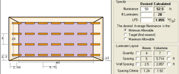
- Quantity- The layout row displays the number of rows and columns in the calculated luminaire grid. To constrain by rows (number of luminaires occurring along the Y axis) or by columns (number of luminaires occurring along the X axis) check the selection box on the outside of the corresponding option.
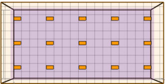
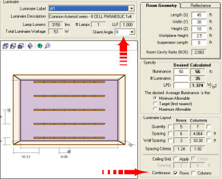
For example: A 50 FC Desired Illuminance request using the Z Lux ZLF1 luminaire results in a layout requiring 28 luminaires producing 52.5 Calculated FC (4 Rows and 7 Columns). To create an alternate layout using 5 Rows and 6 Columns (30 luminaires producing 56 Calculated FC), check the selection box to the left of the Columns cell and change the Column value to 6.
|
Original Layout |
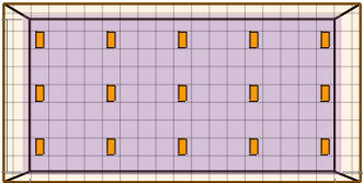
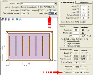
New Layout Constrained by 6 Columns instead |

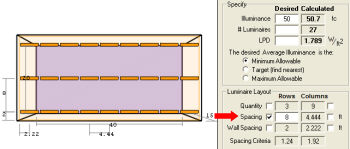
- Spacing - The Spacing row displays the spacing between rows and columns in the calculated luminaire grid. To constrain by rows (spacing between luminaires along the Y axis) or by columns (spacing between luminaires occurring along the X axis) check the selection box on the outside of the corresponding option.
Same example: A 50 FC Desired Illuminance request using the Z Lux ZLF1 luminaire results in a layout requiring 28 luminaires producing 52.5 Calculated FC (5 Ft. between Rows and 5.714 FT. between columns).To create an alternate layout using 8 Ft between Rows instead, check the selection box to the left of the Rows cell and change the Row value to 8.
|
Original Layout |
New Layout Constrained by 8 Ft in between Rows |
- Wall Spacing - The Wall Spacing row displays the spacing between the wall and the luminaire center for the 1st row and columns. To constrain by rows (spacing between the wall and the 1st luminaire along the Y axis) or by columns (spacing between the wall and the 1st luminaire along the X axis) check the selection box on the outside of the corresponding option. It is usually preferred to constrain Wall Spacing by applying and centering a ceiling grid or by applying continuous rows or columns instead.
- Spacing Criterion - The Spacing Criterion row displays the maximum spacing criterion for both rows and columns. If the maximum Spacing Criterion is exceeded (either because the Spacing constraint entered by the user is too large or because the Calculated Illuminance value is too small) the value will appear in red as a visual warning.
- To constrain luminaire spacing to fit within a ceiling grid, apply the ceiling grid by selecting the Apply selection box. Indicate the appropriate spacing between Rows and Columns. To center the luminaires within the room, click in the Center selection box so that a checkmark appears.
- Luminaires are centered within the room and the ceiling grid follows the luminaires centering requirements.
- The lower left corner of the first tile in the ceiling grid is located in the lower left hand corner of the room. Depending on the room size, the tiles located along the top and right side of the room may be truncated. Centering the grid in the room will result in the tiles along each side of the room being equal.
- Luminaire spacings will be calculated in multiples of the specified grid spacings.
- Luminaire Orientation modification may be required to "fit" the selected luminaire within the ceiling grid. For example, specify a 4 x 2 ceiling grid vs. a 2 x 4 ceiling grid will require luminaires to be oriented 90 degrees.
|
2x2 Grid (2 Ft between Rows, 2 Ft between Columns)Luminaire Orient = 0
|
2x2 Grid (2 Ft between Rows, 2 Ft between Columns)Luminaire Orient = 90
|
|
2x4 Grid (2 Ft between Rows, 4 Ft between Columns), Luminaire Orient = 0 |
4 x 2 Grid (4 Ft between Rows, 2 Ft between Columns), Luminaire Orient = 90 |
|
|
|
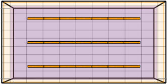
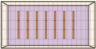
- To constrain luminaire spacing within continuous rows and/or columns, click in the Rows and /or Columns selection box. You may need to apply an Orient angle as well if you desire to align the luminaires end-to-end. If a ceiling grid is applied, continuous rows and columns will ensure luminaires lie in consecutive ceiling tiles, though they may not be end-to-end.
|
Constrained by Continuous Rows, Orient Angle = 0 Degrees |
Constrained by Continuous Columns, Orient Angle = 90 Degrees |
- You may print any of the layouts and the layout comparison by clicking on the Print button. Only valid layouts with the Estimated Average Illuminance > 0 will be available to print.
- You may export any of your layouts to AGi32's Model Mode, including the room size and reflectances, calculation grid, and luminaire locations, by clicking on the Export button. The current layout is exported and the Automatic Placement dialog opens with the work plane selected for the calc points. You may set the point spacing and any other changes that you want and then click OK.