
Calculation Concepts
The Calculate command initiates the lighting calculations in AGi32. When Full Radiosity Method is enabled, both the direct and interreflected light available in the environment contribute to the values. In Direct Only Method, only the direct component from each luminaire affects the calculation values.
Until the Calculate command is executed, all calculation point values are displayed as question marks in the environment. This indicates that no value have yet been determined. The calculation engine used to calculate point-by-point values in Full Radiosity Method is the same engine that produces a rendered environment. If you create an AGi32 environment with surfaces (e.g., Rooms and/or Objects) in addition to luminaires and calculation points, you will have rendered that environment simultaneously when you choose to Calculate.
The Calculate command can also be selected in Render Mode when Full Radiosity Method is enabled. By calculating in Render Mode you can see the evolution of the radiosity process during calculations. This mode allows you to gauge the validity of your design and, if necessary, stop the calculations before they are complete so that changes can be made.
There is no difference in calculated results between calculating in Model Mode or Render Mode. However, calculations will take slightly longer in Render Mode because of the display updates.
Calculations may be paused and resumed in Render Mode as desired. All interactive navigation commands are active while the calculations are running. (Exception: Navigation commands not available during roadway calculations.) Calculations will pause during navigation.
Multi-core, Multiple Processor, and Hyper-threaded Environments
AGi32 will automatically take advantage of the potentially significant extra speed possible with multi-core and multi-processor computers with more than two cores. With two cores or fewer, there may not be a time advantage, and AGi32 will therefore not attempt to use the second core. Hyper-threading combined with multiple cores conveys a small increase in calculation speed, on the order of 10% or so. These default settings may be changed with the System Settings command.
Processing Priority
AGi32 automatically applies a lower processing priority whenever another application has focus during the calculation process. For example: If you open Outlook while calculating, AGi32 will automatically relinquish resources to Outlook, allowing it to operate with minimal interruption. Therefore, it may not be necessary to Pause calculations in order to execute other tasks.
Pause/Resume is only available while in the Full Radiosity Method during the radiosity and calculation points steps. It is NOT available in Direct Only Method or during Roadway or Glare Rating point-by-point calculations.
With the exception of roadway calculations, the following commands are active while calculating in Render Mode or when Paused in Render Mode:
- Default views
- Interactive commands
- View Manager
- Display Properties
- View Properties
- Status Bar – Textures, Wire Overlay, Model Overlay, Anti-Aliasing
Selecting commands during the calculation process may not take effect immediately, depending on where the program is in the calculation process. Therefore, it may be necessary to click the command multiple times before it becomes active. Note: The program is generally more responsive after the adaptive subdivision step.
Pausing the calculations allows for more responsive interactive display manipulation (smoother image display). This may be necessary on computers with limited resources.
AGi32 uses Radiosity techniques to calculate when the Full Radiosity Method is used.
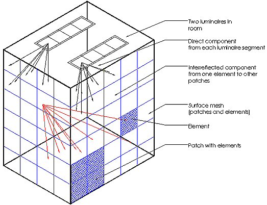
Radiosity is a global illumination technique used to process interior and exterior environments where luminaires and surfaces are defined. Global illumination describes the interaction between objects and/or rooms with the light sources and each other. In AGi32, each surface on every entity is broken up into smaller pieces, called patches. Each patch is divided into additional pieces, called elements. Patches emit light, elements receive light. Each patch reacts with the other elements that are visible to it by reflecting light towards them. The process of distributing the light between surfaces is known as a step.
The Rendering process begins by emitting the light from the luminaires to those elements visible to them. Each element will absorb and reflect a certain amount of light, depending on its reflectance. AGi32 optimizes the rendering process by identifying the patch (a collection of elements) that receives the most light and makes it a secondary light source. The process is then repeated by calculating the transference of light between these patches and all elements visible to them. At each step, the luminance values at the vertex of each element (calculated from the received light) are accumulated and tabulated.
The process is repeated, one step at a time, until the amount of light remaining unabsorbed in the environment is very small (compared to the original amount of light emitted by the light fixtures), unless the calculations are stopped manually by the user. The total amount of light reflected by each patch is added up and the luminance for each patch is calculated.
Patch/Element Sizes
Patch and elements sizes are specified internally based on the surface size. Larger surfaces are broken up into bigger patches and smaller surfaces are broken into smaller patches. Each patch is subdivided automatically into elements, using the default Element Size Factor (default factor = 0.5, 4 elements per patch).
You may apply different meshing parameters to each individual surface using the Surface Edit command.
Unlike Adaptive Subdivision (AS), Adaptive Patch Subdivision (APS) is always enabled regardless of whether AS is enabled or not. In addition, APS does not modify the Patch-Element geometry; it simply reassigns each Element of a given Patch as its own Patch.
There is no significant performance hit in terms of memory or CPU time. Therefore, this feature is entirely transparent (apart from results) to the user.
APS is applied in two different situations:
- High levels - patches are subdivided if their initial unshot flux exceeds 50% of the Patch with the most unshot flux. In layman's terms: Spreads out the "hot" spots.
- Low levels - Patches are subdivided if the difference in Element exitances for the Patch exceed 10:1, and the maximum Element exitance is greater than 1.0E-06 times the maximum element exitance for the entire environment. In layman's terms: Minimizes "Patch leak."
Caveats for APS in "low level" situations:
- Light leaks will still occur if a surface straddles the refined Patch such that their centers are on the "dark" side.
- Even if there are no light leaks, the OpenGL rendering may show what appears to be light leaks; this is a rendering artifact, not unique to AGi32.
Radiosity Limitations
Radiosity techniques are currently limited to diffuse surface calculations. You may model the effect of shiny or specular surfaces in AGi32, such as chrome, marble or glass, for visualization purposes using post process Ray Tracing, however, these non-diffuse surface attributes will not be considered for calculation purposes.
Advantages of Radiosity
- Color Bleed – The light emitted from a surface carries the surface color with it. Light color in AGi32 is additive, so that light color mixes together as we would see it in real life.
- For example, place a piece of bright colored paper close to a white wall and shine a flashlight on it. Even under normal room illumination, you will likely see a strong blotch of color reflected from the wall.
- Soft Shadowing – Shadowing is captured because of the surface meshing (one patch is distinct from its neighbors) Finite shadows can be produced by breaking up the surfaces into small enough patches.
- Global interactivity – you can look at the environment from any point of view without having to recalculate because the surface luminance for each patch is the same in any viewing direction.
Coplanar Polygon Merging (During Surface Meshing)
Many imported CAD objects are poorly constructed in terms of radiosity calculations and rendering. For example: A round surface is typically constructed of several long and skinny triangles which commonly lead to rendering artifacts. To alleviate these artifacts, AGi32 examines each surface during the meshing process to determine if the surface is constructed of multiple polygons and, if so, merges adjacent polygons into a single polygon. This reduction in polygons has a direct affect on calculation time and reduces rendering artifacts.
Note: The coplanar polygon merging feature requires an exceedingly complex algorithm with a number of heuristics to handle problem surfaces that may include extremely small polygons or holes. While every attempt has been made to anticipate every possible variation of surfaces, there will most likely be environments that the program cannot handle properly.
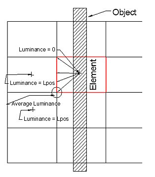 Radiosity techniques assume that the gradient of light
across an element is linear. The luminance is calculated at the center
of each element. The element vertices are calculated by calculating the
average of the surrounding elements and a linear gradient is interpolated
in between. Imagine that you have an object intersecting an element. The
luminance calculated outside the object at the element center would be
positive. The luminance calculated at the elements underneath the stack
would be 0. The luminance would be graduated from the center of the element
to the vertices and not sharply cut of at the stack boundary. This phenomenon
is known as patch leak.
Radiosity techniques assume that the gradient of light
across an element is linear. The luminance is calculated at the center
of each element. The element vertices are calculated by calculating the
average of the surrounding elements and a linear gradient is interpolated
in between. Imagine that you have an object intersecting an element. The
luminance calculated outside the object at the element center would be
positive. The luminance calculated at the elements underneath the stack
would be 0. The luminance would be graduated from the center of the element
to the vertices and not sharply cut of at the stack boundary. This phenomenon
is known as patch leak.
Patch Leak is minimized by the (automatic) application of Adaptive Patch Subdivision. (See above.)
Typically, applying adaptive subdivision is the simplest method to repair patch leak. However, sometimes the elements cannot be made small enough to completely eliminate the patch leak. In these situations, there are several alternative that may be employed to create more realistic imagery:
- Produce a Ray Trace image and Ray Trace Direct Illumination (for visualization purposes only).
- Assign a finer mesh to the surface exhibiting the patch leak using the Surface Edit command. Use the Mesh Level attribute to assign an initial denser mesh.
- Apply the High Setting of Adaptive Subdivision instead of the default setting.
- Remove the calculation points under the solids (e.g. under the racks) if these are showing small positive values.
- Build the surfaces separately (e.g. in a cove application, build the wall and cove as a vertical extrusion object instead of using multiple objects so that the single wall is not created above and below the cove)
Radiosity Stopping Criterion - Accuracy vs. Calculation Times
AGi32 processes the Radiosity calculations until the Stopping Criterion is met. Stopping Criterion indicates the amount of unabsorbed light that can remain in the environment before the Radiosity calculations are stopped. The default Stopping Criterion is 99%
For most Electric lighting applications, the environment will show little numerical change (the FC results will be stable) at a Stopping Criterion of 95%
For Daylighting applications, the calculations should not be stopped until the default Stopping Criterion is reached (99%) as the values can still fluctuate above acceptable tolerances.
Exitance Meter vs. Virtual Meter
When each meter is applied:
- Exitance meter - The Exitance meter is applied whenever Automatic Placement Calculation points are created on reflective surfaces.
- Virtual meter - The Virtual Meter is applied whenever calculation points are placed manually in the layout (grids, polygons, scattered calculation points, lines of calculation points). The Virtual meter may also be used when Automatic Placement is applied in the following cases:
- The reflectance of the associated surface is 0 or transmittance is greater than 0.
- The associated surface has been removed from the room.
- Automatic Placement points are placed on a workplane (in a room).
- The light meter has been changed and is no longer normal to the surface.
- Automatic Placement points exist over an opening. If the distance from the calculation point to the associated surface exceeds 0.5ft or 0.15M, the program automatically switches to the Virtual Meter
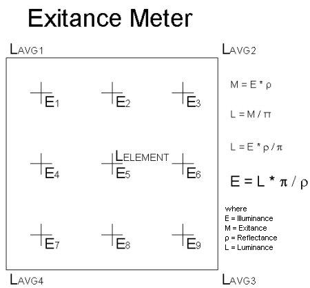
The Exitance meter calculates Exitance or Illuminance values on surfaces using the luminance values from the elements. If the elements are too large to accurately capture the gradient of light across them, then the calculated values will reflect this limitation. The virtual meter calculates Illuminance by using an independent calculation meter, which looks at the direct component of light and the reflected component of light from the surfaces that are visible to it. The virtual meter is the most accurate meter type.
The Exitance meter calculates much faster than the Virtual meter. It should be used whenever possible, except in special cases.
Special Cases
In cases where the luminaires is positioned very close to the surface with the calculation points, the Exitance meter may not accurately calculate the illuminance values for large patches. The linear gradient assumed across the patch is not accurate in these cases, unless the patches are small.
You have three options in these cases:
- Use a manually positioned calculation grid or polygon, so that the Virtual Meter is used.
- Apply adaptive subdivision, to decrease the element size based on the photometric distribution.
- Manually change the meshing parameters for the nearby surfaces using Surface Edit so that the patch size is decreased.
- Advantages – Small patch size leads to more accurate gradients across patch.
- Disadvantages – Patching is applied to all surfaces, increased calculation time.
Calculation Method Ramifications
The Calculation Method choices allows you to select whether direct only or direct and reflected light will be considered in the calculations.
Luminaires are applied differently in each method, and your results may vary based on these differences. Further discussion is provided below.
In general, Full Radiosity Method should be used in most cases, especially where reflected light is a major contributor and you wish to render the results. Daylighting can only be computed in Full Radiosity Method .
Direct Only Method provides faster results because it does not consider inter-reflected light. The Direct Only Method does consider the obstructive properties of Rooms and Objects in the calculations. All Rooms and Objects are considered as opaque, non-reflective surfaces in the Direct Only Method regardless of their original specifications. The Direct Only Method will not compute daylight component.
Calculation Method Applications
Consider the following examples to help you decide which mode will suit your requirements:
Interior
In most interior applications, interreflected light is very important so the use of Full Radiosity Method is most common. However, if you wish to evaluate only the direct contribution from the luminaires to the calculation points, while considering the obstructive capabilities of objects, switch to Direct Only Method and recalculate. While in this mode you will not be able to see the rendered view.
Site Lighting or Interchange
- Reflective and obstructive objects need to be created in order to take advantage of Full Radiosity Method. Use the Automatic Placement command to place calculation points on a planar object representing the ground or roadway plane in addition to other objects. It is now possible to render the environment.
- In the case where no reflective objects are to be considered but rendered results are wanted, use Full Radiosity Method. Place Automatic Placement points on a planar object representing the ground or roadway plane.
- Obstructive capabilities of objects are desired. Use Direct Only Method. Specify the objects that obstruct light in the environment. Rendered results are not available.
- No reflective objects are to be considered and rendering is not required. Use Direct Only Method. Place calculation points using calculation Grids, Polygons or Lines. Rendered results are not available.
Sports Lighting
Start by placing calculation grids and polygons in Direct Only Method. You may also place objects in the environment to consider their obstructive nature (elements such as scoreboards or bleachers).