
Object Concepts
|
|
|
|
Objects are used to model many shapes in AGi32. The choices of object shapes available are varied and range from simple geometries like rectangles, cylinders (Round-Flat Object) and spheres to customizable shapes with irregular profiles. Objects can be inserted into any environment, both interior and exterior to block, reflect and transmit light as necessary. In addition, single or multiple objects may be stored in a user-defined "library" of objects. Library objects can be recalled at anytime, modified for scale and color or reflectance and be placed in any job file. AGi32 is delivered with a number of factory provided library objects that may be used at any time to add detail, scale and realism to any lighting layout. However, the strength of the system is the ability to create your own object libraries relevant to your work and draw from them whenever necessary.
|
AGi32 is also capable of importing three dimensional solids created in other software via DXF or DWG files. Imported solids are converted into AGi32 objects and can be manipulated using the object commands. Generally, imported objects are composed of large numbers of small surfaces. These objects can be difficult to edit for color and reflectance once imported. Ideally, an externally created object will be stratified into multiple layers and blocks. This makes the process of assigning color, reflectance and texture relatively simple on import. The internal modelling tools offer substantial flexibility when creating complex elements by using a combination of object shapes. The palm tree object, shown at right, was created by using a Round-Flat object to create the cylindrical trunk and Planar objects to create the leaves. One leaf was created as a template and multiples were added using the Rotate Object and Polar Array Object commands. By visualizing the basic shapes that make up real forms in the environment, you can make your layouts more realistic. |
|
Dialog Defaults
The individual parameters available in all Object dialogs are automatically saved and restored in the Object dialogs. There are two types of defaults present in all of the dialogs: Global and Local. Global defaults occur in every Object dialog and carry over to other Object dialogs as well. Local defaults only occur in specific dialogs. The following defaults are global for all Object commands.
- Label: Default Label is Object. The Label name will automatically increment to produce unique labels. For example, if the first Object is labeled Object, the second is labeled Object_1. When the default label is changed, it will also automatically increment.
- Wireframe color
- Labeling options
- Height of Sides
- Top, Sides and Bottom surfaces: Color, Reflectance and Texture (including applied options).
Reset Defaults - Selecting this button will reset all Global dialog parameters to the factory defined specifications.
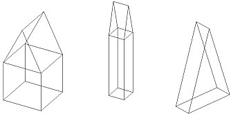
Object Shapes
|
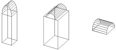
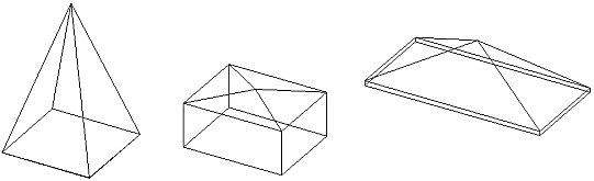
Rectangular Barrel Vault Objects |
|
|
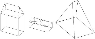
Rectangular Gable Objects |
|
|
Rectangular Hip Objects |
|
|
Rectangular Pyramid Objects |
|
|
Rectangular Flat Objects |
|
|
Rectangular Flat Object combination |
|
|
Rectangular Vertical Extrusion Objects |
|
|
Rectangular Vertical Extrusion Object combinations |
|
|
Round Cone Objects |
|
|
Round Flat Objects |
|
|
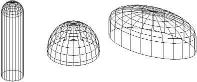
Round Dome Objects |
|
|
Round Sphere Objects |
|
|
Round Vertical Rotation Objects |
|
|
Polygon Flat Objects |
|
|
Polygon Flat Object combinations |
|
|
Polygon Vertical Extrusion Objects |
|
|
Polygon Vertical Extrusion Object combinations |
|
|
Planar Objects 1 - Triangular 2 - Trapezoid 3 - Quadrilateral 4 - Polygon |
|
Object Dimensions
All Object types have certain dimensional variables associated that describe some parameter of the shape that must be defined prior to creating it in the graphics area.
|
|
|
|
|
|

|
|
|
|
|
|
|
|
|
|
|
|
|
|
|
|
|
|
|
|
|
|
|
Aspect ratio - The Aspect Ratio is used to define the shape of the sphere equator. An Aspect Ratio equal to one will create a perfectly round spherical equator. Aspect Ratios greater than one lengthen the X-axis of the base resulting in an elliptical shape left to right. Aspect ratios less than one elongate the Y-axis of the base to form an ellipse aligned top to bottom. As an example, an Aspect Ratio equal to two will create an ellipsoidal object that is twice as long in the X-dimension as it is in the Y-dimension. An Aspect Ratio equal to one half (.5) will create an ellipsoidal equator that is twice as long in the Y-dimension as it is in the X-dimension. |

Surface Properties
Surface properties of Color and Reflectance must be defined for all object surfaces. Color and Reflectance are related to one another in a way that allows only certain colors to be assigned to a specific reflectance value. This is a mathematical relationship that is discussed in more depth here. To alter the color or reflectance of an Object surface, click the mouse in either the color or reflectance cell.
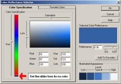 By default, the colors shown are shades of gray based
on the reflectance entered in the adjacent cell. You can select any reflectance
within the gray scale range (Black to white) by entering it in the reflectance
cell provided.
By default, the colors shown are shades of gray based
on the reflectance entered in the adjacent cell. You can select any reflectance
within the gray scale range (Black to white) by entering it in the reflectance
cell provided.
To select a color, move the Hue slider to the desired color, then move the Saturation and Luminance sliders to achieve the desired color. The reflectance will be calculated and displayed. You can adjust the reflectance within the Hue by moving the reflectance slider.
Textures
Texture are graphic images that may be applied to the object surfaces to make them appear more realistic. Textures like brick, stone, concrete and wood can be tiled in a repeating pattern across the surfaces or stretch across them. The average reflectance and color of the texture is calculated and used instead of the surfaces original color in the radiosity calculations.
AGi32 comes with a selection of assorted textures that may be applied to any surface. You may also obtain textures from lots of other sources, including free texture sites online, commercial texture collections, even use your digital camera to obtain them directly. Click here to read about texture tips.
To apply a texture to a surface, click in the Texture cell. Select the texture from the Texture database, then determine the application options.
Advanced Surface Properties
Open/Closed Objects
Certain round object types, such as cones, spheres and vertical rotation shapes can be Open or Closed and can reflect light on the outside or inside. In the case of transmittance >0, the object will have reflectance/color on both inside and outside unless "closed."
Open Shapes
When the Open option is selected, the object base is removed (for cones and vertical rotation objects) and any partial sides are also left open. Open objects may be closed at a later time by editing the object and unchecking the Open selection box.
Reflective Side
When working with open shapes, reflectance/color can be specified to be on either the inside or outside of the object. Generally, it is imagined that "open" shapes will be reflective on the inside or will be assigned a transmittance. "Closed" partial shapes would most likely be reflective on the outside only.
Inserting curved surfaces into object (Polygon-Flat, Polygon-Vertical Extrusion, Planar, Rectangular-Vertical Extrusion and Round-Vertical Rotation)
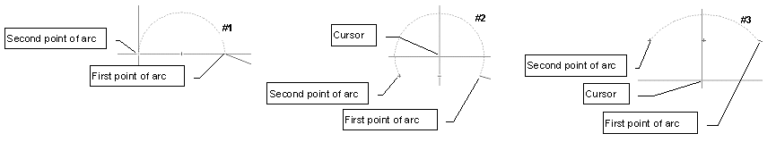
It is a simple procedure to describe a curved surface using an integrated Arc function. An arc can be fit between any two points and can be of most any radius. To insert an arc into a building, press the F4 key on your keyboard at the starting point of the arc. The command prompt (lower left corner of screen) will then prompt for the second point of the arc as shown at right. Click the mouse at the second point of the arc and a dotted line will appear showing the current arc shape. If you don't move the mouse the initial arc will be a perfect semi-circle (#1). Move the mouse cursor toward the arc apex to raise the arc center point and increase the circumference (#2).Or, move the cursor away from the apex of the arc and move the arc center downward. This effectively flattens the arc (#3).
Reversing the Arc
The direction of the arc can be reversed by simply pressing the F5 key on your keyboard.
Curved surface resolution
Curved surfaces are automatically divided into a series of straight segments based on the setting of the system variable Initial Curve Increment (degrees). The default is 15 degrees. This is adequate for most applications. This variable can be found under System Settings command from the Tools menu. Click on the Defaults tab and then on the Advanced button.
Removing Surfaces
AGi32 provides the ability to eliminate surfaces from any object shape you might create by removing the surfaces. Removed surfaces are not considered in the calculations any longer. A removed surface behaves differently than one whose reflectance is set to zero. Surfaces that have zero reflectance absorb all light that touches them and reflect no light outwards. Removed surfaces allow light to transmit directly through them because they no longer exist (unless another surface exists in the same location). Once surfaces are removed, you can recreate them by changing their reflectance to a real value.
By removing selected surfaces in the object, you have the ability to append other shapes to the object. These shapes may in turn have their surfaces removed. Continuing in this fashion, you can create very elaborate models consisting of numerous objects joined together. For example, you may want to create an Rectangular-Flat object and remove one of the sides that was initially created to create the base for a bookcase. Once the side is removed, you can use any combination objects to create a custom shelving unit.
To remove a surface, either Edit the object and select the Surface Edit button in the Edit dialog or use the Surface Edit command to select the object. In the Surface Edit dialog, navigate to the surface you wish to remove. To remove more than one surface in an object, Tag all of the surfaces you need to operate on. Change the Surface Type to Removed (Invisible) and click Ok.
The surfaces will be removed from the environment. In Model Mode, they will appear as dashed lines, in Render mode, they will simply not appear. Removed surfaces can be replaced at any time through the Surface Edit dialog by changing the surface back to a Single Sided or Double Sided surface with appropriate reflectance/color.