
AGi32 requires that a luminaire be defined before it is located in the job file. This is done from the Define button in the Luminaire Toolkit, or from the Add menu, select Luminaire - Define command. The luminaire definition includes a reference Label, optional descriptive fields for the luminaire, photometric information, luminaire symbols, and your selected luminaire arrangement details. Each luminaire instance placed in the job file will access these parameters in addition to the aiming information specified by the user.
Once a luminaire has been defined, it can be used repeatedly. The defined luminaires represent a catalog of luminaires that can be conveniently located in the AGi32 Model area. Luminaire definitions can be added, edited or removed at any time. AGi32 places no limits on the number of luminaire definitions.
Coming from an earlier version of AGi32? Please see our Define dialog comparison.
With the remodel of the Define dialog for AGi32 version 20 the process of defining a luminaire is completely automated. Luminaires are ready to use as soon as they are shown in the defined list (the grid). Any modifications you make are automatically committed we soon as the cursor focus leaves the input cell by tab, enter of click). If you enter data in a cell and do not move focus, an Apply button appears on the toolbar. You must leave the cell or click Apply to commit the change.
Once a luminaire has been defined, it may edited at any time. To redefine a luminaire, invoke the Define Luminaire dialog box (Define Luminaire button or Modify - Luminaire - Definition command on the main menu bar). Highlight the desired luminaire in the grid and make the desired modifications. This might be as simple as a light loss factor change or as involved as the selection of a completely new photometric file to be assigned to the label. Move the cursor focus with the tab or enter key, or click the Apply button.
Once redefined, all occurrences of that luminaire type already present in the model will be changed to reflect the modifications of the redefined luminaire. If AutoCalc is enabled, AGi32 will recalculate all analysis points.
Dialog Sections
Retrieving luminaire photometric data is your fist step towards building a usable definition. We have automated all of the processes from that point forward. This means that once you bring in a photometric file in STEP 1 below, you instantly have a useable definition. Many changes can be made to that definition as emphasized in the remaining STEPS (below), some that should be standard (EX: light loss factor), but they are all optional. When making a change to any field either in the Grid or the Panels you need simply exit the field to record the change. If you edit a field and do not leave that field, an Apply button is available at the top of the dialog to cement the edit.

STEP 1 - Access photometric file(s)
Access luminaire photometric files using one of the following methods:

- Browse/Recent button: The Browse/Recent dialog provides easy access to any photometric files on your computer system. You can browse folders (Browse tab)or see all recently accessed files from the Recent tab.
- Collections: Select previously defined luminaires stored in Luminaire Collections. Collections are groups of luminaire definitions saved for repeated use.
- Import: You can import luminaire definitions from any saved AGi32 job file. (See Photometric File Selection).
- Instabase: Select photometric data from leading manufacturers
using the Instabase (Instabase Help). You can use your Default browser or the Microsoft Embedded browser from the pull-down menu:
- Connect via Embedded Browser. This option opens a browser window that is "embedded" in your working instance of AGi32. Once you have selected one or more files and clicked on the link to Download to AGi32 or Save To Zipped File, the browser closes. You must have the latest version of Internet Explorer (version 10 or higher) to access Instabase this way.
- Connect via Default Browser. This option opens your default browser (e.g., Chrome, Firefox). From there, you may drag-and-drop selected files into the Define Luminaire dialog. The browser window does not close automatically, enabling you to return to it without initiating the Instabase command again.
- You may need to add *.agi32.com to your list of trusted sites in order to use the drag-and-drop feature.
- For this method, you do not need to have the latest version of Internet Explorer if you have a different browser set as your default.
- Drag-and-drop a photometric file from a different location on your computer directly into the grid area where the defined luminaires are listed.
STEP 2 - Smart Symbols and Symbol Selection
When selecting photometric files the Smart Symbols dialog will open automatically for each selected file. Smart Symbols will assist you in selecting an appropriate symbol by extracting the luminaire's luminous shape and distribution from the photometric file. Select an appropriate mounting type and AGi32 will suggest symbols for you based on the photometric file dimensions, light distribution and mounting selected. Most symbols "flex" meaning they will be scaled to the luminous dimensions contained in the photometric file. Once the symbol is selected, it is used in both Model and Render modes. After the Smart Symbols dialog closes the luminaire definition is complete. You can revise symbols in the Define dialog at any time as discussed below. For more detail on symbols see the luminaire Symbols topic.

Symbols adjustments available in the main Define dialog

Calculation symbol characteristics:
- Housing Color: Click in the Housing Color cell to change the colored appearance of the symbol in Render mode.
- Luminous Area Color: Click in the Luminous cell to change the color of the light emitted by this luminaire. There are several options and they behave differently in terms of calculations. Please see the topic SRE Color for details.
- Insertion Point: The symbol insertion point is the point to which the symbol will be attached to the model cursor when placing luminaires. It also refers to the relationship of the symbol housing to the luminaire mounting height (Z-coordinate) when the symbol is placed. Symbol insertion point defaults are selected initially for your symbol choice in Smart Symbols. The insertion point can be adjusted both vertically and horizontally by clicking the Insertion Point button to open the small dialog below. This dialog is a subset of the main Symbols dialog and the settings are redundant. See also Symbols Concepts topic for Insertion Point details.
Insertion point dialog

Drawing symbol characteristics:
- Wireframe Color: The Wireframe color is the color of the line drawing in Model mode.
- Line Width: The default line width is 1 pixel. You can change it here in terms of scaled units (ft or m)
Changing symbols once a luminaire is defined is easy, simply click in either one of the symbol fields in the main Define dialog: Calculation or Drawing, or in the symbol representation in the grid if you have included it there. The main Symbols dialog will open (shown below). By default the Calculation and Drawing symbols are linked together. Selecting a new Calculation symbol will also provide a new Drawing symbol of the same shape and size. You can unlink the relationship between the two symbols by selecting the check box titled Different Drawing Symbol in the Drawing Symbols area. Once unlinked you are free to assign a different symbol for Drawing mode. For details on the various options available in the Symbols dialog please see the Symbols Concepts topic.

Some luminaires in the Instabase have custom luminaire symbols associated with them built by the manufacturer. When these photometric files are selected, the luminaire symbol is included and the Smart Symbols dialog is bypassed. This can also apply to the other photometric file access methods when custom symbols are present in the same folder as the photometric file (see hyperlink).
The General section contains input fields for luminaire Label, Description and Tag. Only the Label field is required input. The default responses for Label and Description can be selected from the System Settings area. The factory default for Label is the luminaire filename. The default for Description is the response from the IES file [LUMCAT] keyword. The Tag field is left empty by default. By using intelligent default responses your luminaire definition is ready to use immediately. You can change the responses as desired.
- Label: The luminaire Label is used to identify the specific luminaire type. By default, the luminaire Label is specified per the settings in the Default Label in System Settings. To change the Default settings for future definitions, click the Settings button. You may also manually assign a unique label of your choice. There is no longer a limit of the number of characters permitted. To change the Label of an already-defined luminaire, simply enter the new Label in the Grid or Panels section and press tab to leave the field.
- Description: Descriptions are used to further identify a particular luminaire type. By default, the luminaire Description is specified per the Description Defaults in System Settings. You may also manually assign a Description of any length. You can paste from a text editor such as Notepad if you like.
- Tag: If a non-unique identifier is desired, you may assign a Tag. Click on the Concepts tab (top of this topic) for more information on Luminaire Tags. There is no limit on the number of characters in a Tag.
- Filename: The photometric filename is displayed here. You can replace the photometric file in the definition by clicking on the folder icon to select a different file (see below). Use the eye icon to view the contents of the raw photometric file.
- Replace Photometric file icon:
- Replace Photometric File - Replaces the photometric file of selected definition (Single or Arrangement) with a newly selected photometric file. You can replace the photometric file for one definition at a time.
- Three possibilities exist when replacing the photometric file:
- Luminous Box has same shape and size - Replacement proceeds w/o feedback
- Luminous Box has same shape but different size - Current symbol is scaled per selected photometric file and user is notified accordingly
- Luminous Box has different shape - No changes to symbol are made, user is notified along with a note suggesting to select more appropriate symbol after replacement is complete
- Photograph: If there is an image associated with the photometric file (most common when coming from the Instabase), it will be shown. Images can be associated with files on your local system by placing a JPG or PNG image in the same folder, using the same filename, less extension (best practice is to limit images to no larger than 512x512, square is best). Example: photometric_file.IES could have image file of photometric_file.JPG.

The Attributes section can contain any text information you wish to assign to a luminaire definition and Attributes can be included in the Luminaire schedule. Attributes are created in the Settings dialog (Luminaire Define section of System Settings) and we provide several common possibilities for you, shown in yellow highlight. You can remove these if you do not want to use them by removing the check mark in the Settings dialog.
Add your own Attributes using the Add button. Smart Attributes can pull information from the IES file such as keyword responses, or reference other Define dialog fields or calculated metrics as shown by {data} in Settings. Be sure to read all about Attributes in the separate topic: Luminaire Define - Attribute Section.

A few rules on Attributes
- Attributes can be added, removed and organized in System Settings using the buttons above the left column
- Attributes are job file specific (you can use different attributes in different files)
- Factory Attributes are enclosed in <>'s
- Factory Metrics (Grid Columns) are enclosed in { }'s
- User Attributes created from the Add button cannot contain <>'s or { }'s
- Select Attributes on the right to add to your Grid
- Attributes in a job file are automatically added to the Attributes list and added to Columns if enabled when opening
- Reorder Attributes using Alt+Up/Down arrow keys
- Factory attributes can be restored by resetting defaults in System Settings
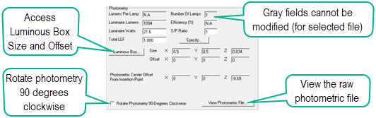
STEP 5 - Photometry Section
The Photometry Section pulls some information from the photometric file while calculating data for other fields. Fields that appear gray cannot be edited.
- Lumens per Lamp: For relative photometry this figure comes from the photometric file and can be edited. For absolute photometry this field will read N.A. as the lamp lumens value does not exist (it is shown as a negative one in the IES file).
- Number of Lamps: For relative photometry this figure comes from the photometric file and can be edited. For absolute photometry this number comes from the photometric file but cannot be edited.
- Luminaire Lumens: This value is calculated from the luminaire zonal lumen output. It is the total lumen value emitted from the luminaire. This is a calculated field and cannot be edited.
- Efficiency (%): For absolute photometry this field reads N.A. (it is 100%). For relative photometry the efficiency is the luminaire lumens divided by the lamp lumens in percent.
- Luminaire Watts: The value for this field comes from the photometric file. It should be the total luminaire watts, not lamp watts (relative photometry). This field is used to calculate Lighting Power Density (LPD) and can be edited.
- S/P Ratio: This number is the Scotopic/Photopic ratio and is one by default. It can be changed manually for the calculation of Mesopic results.
- Total LLF: The Total Light Loss Factor can be entered manually or can be calculated using the Specify button which contains common components considered in the TLLF.
- Luminous Box: These values are the luminaires luminous dimensions from the photometric file (see also Luminous Box)
- Rotate Photometry 90 Degrees Clockwise: This checkbox is supplied primarily for European luminaires tested with C0 (0 H) parallel to the curb. This is 90 degrees off from IES standard where zero is typically perpendicular to the curb (pointing into the street). This function rotates the photometry but not the luminous box.
- View Photometric File: This button will open a window to display the raw photometric file (ASCII text). You can copy and paste form this window.
Metrics Section
The Metrics section does not require any input and cannot modify the luminaire definition. It provides graphical representations of the photometric intensity (top) and of the lumen distribution for the Luminaire Classification System (LCS/BUG). It also provides a list of calculated metrics useful in understanding the luminaire performance. The More button will enlarge the two graphical representations and allow some customization of their appearance.

STEP 6 - Configuration Section (Arrangement/Pole/Pendant)
The Configuration section contains the Pole and Pendant selections and luminaire Arrangement selection, Arm and Offset (hidden when not applicable). For more details please see the Arrangements topic.
- Pole or Pendant: Add a pole or pendant to be displayed with this luminaire type by clicking in the appropriate box. Poles and pendants can be static or dynamic entities. Poles and pendants are considered to be physical entities when calculating using the Full Radiosity Method and may obstruct the light emitted from the luminaire and cast shadows in the visualization.
- Arrangement: Select a luminaire arrangement from a number of
factory supplied arrangements. Click in the Arrangement box
to bring up the Luminaire Arrangements dialog. Depending on
the selected arrangement, you may be able to specify the luminaire's Arm
Length and Offset. Arrangements consist of multiple instances of the current luminaire arranged around a single point. For multiple occurrences of different luminaires please see Groups.
- Arm Length: This dimension is applied from the symbol insertion point in the 180 photometric plane. It is the distance from the insertion point to the pole. See the Arrangements topic.
- Offset: This dimensions is applied from the insertion point of the symbol in the 90-270 photometric plane. It is the distance from the insertion point, or the end of the arm if applied, to the pole.

You can build your own Custom Arrangements easily and can even build from one of the Factory arrangements by using the Copy button. Read all about Custom Arrangements here.

Buttons
Copy a Luminaire Definition
Select the definition in the grid and click the Copy button on the toolbar, or open the right click menu and select Copy. The Label will be automatically amended with an underscore and a number corresponding to the number of copies. Change the Label as desired.
Deleting Luminaire Definitions
Select the luminaire definition(s) in the grid (shift-click or ctrl-click for multiple) and click the delete button on the toolbar, press the Delete key on the keyboard, or open the right click menu and select Delete.
Open Photometric Toolbox (PTB)
If you have the current version of Photometric Toolbox installed you can take the selected photometric files to that software for inspection. Any modifications you may have made to the Number of Lamps or Lamp Lumens (relative photometry) will be shown in PTB and reflected in calculated metrics. See More about... below.
Audit Luminaire Definition(s)
Select the luminaire definition(s) in the grid (shift-click or ctrl-click for multiple) and perform and Instabase Audit on the photometric file(s) selected. The Audit function attempts to locate the same data in the Instabase to see if there is a newer version of the file available. See the Audit topic for more information.
Add to a Collection
Select the luminaire definition(s) in the grid (shift-click or ctrl-click for multiple) and click the Collections button, or open the right click menu and select the Save to Collection command. This will open the Collections dialog. More information on Collections.
Right-Click Menu Functions
Replace Photometric File
Select the luminaire in the grid. Open the right click menu and select Replace Photometric File. This will open the Browse/Recent dialog to locate a new photometric file. You will see a message if the luminous shape or dimensions are different allowing you to select a new symbol, scale existing symbol or ignore* and use the current symbol.
* If you select Ignore be aware of the ramifications. You will want to confirm the luminous box is not penetrating any surfaces or is not misaligned. Turning on the Luminous Box overlay in Render mode Display Settings will be valuable.
Change LLF
To change the light loss factor for a single luminaire you can simply type over the value in the Grid or Panel fields and tab to exit the field. If you want to change the LLF for multiple luminaires at one time, select the luminaires in the grid, open the right click menu and select Change LLF... Enter the new LLF and click OK.
Open File Location
Select a definition in the grid, open the right click menu and select Open File Location to open a Windows Explorer dialog showing the file location on your computer system.
Select Columns to Display (grid)
Open the right click menu and select Columns to Display command. This will open System Settings to allow you to change the columns you have displayed in the grid.
Changing Luminaire Label
Simply type over the current label in the Grid or Panel fields and tab to exit the field. You have now changed the Label for all luminaire instances assigned to the previous label.
General Editing in the Grid
You can edit any of the text input fields in the grid by clicking in that field and typing. You can also access the Arrangement and Symbols selection by clicking in those cells if present in your grid. Clicking on the Polar display will open the More dialog (identical to the button).
Sorting and Reordering Defined Luminaires
Defined luminaires can easily be sorted by clicking the appropriate column header in the grid. In addition, the list can be reordered for scheduling purposes by selecting a Label and then pressing Alt + Up Arrow key to move up in the list and Alt + Down Arrow to move down in the list.
Note: Columns in the Grid can be resized if necessary. Simply move the mouse over the column separator (beginning or end of column) until the resize icon appears. Drag left/right as needed.
More About Accessing Photometric Toolbox from within the Define Luminaire dialog
By clicking on the Photometric Toolbox button on the toolbar you can open the selected files in Photometric Toolbox (PTB) to examine a luminaire's characteristics more closely. You can select up to 25 definitions prior to clicking on the PTB button (PTB opens 25 max). The photometric file for Single or Arrangement is loaded into PTB. Luminaire Groups cannot be loaded into PTB.
The photometric file loaded into PTB is an IES file generated by AGi32 using the specified data in the definitions. This file will reflect any changes that you have made to the Lumens Per Lamp and Watts fields. This might be useful to generate a report based on prorated Lumens Per lamp or different Luminaire Watts. The keyword [_AGi32] is included in the description as a reminder of where the file was generated from.
The file generated by AGi32 is saved in your PhotometricData_FileFromJobFile folder (see Tools - System Settings). The filename (as displayed in PTB) is generated from the define luminaire label with '_AGI32" appended. You can, of course, save the file as a different name with Photometric Toolbox.
You want to compare a defined luminaire with another file on your system without having to load it into AGi32? No problem: Select the defined luminaire in AGi32 and open Toolbox by clicking on the PTB button. Now you can drag-and-drop the file you would like to compare it to directly into PTB.