
AGi32 is able to import CAD-created backgrounds in either DXF or DWG file formats. Three-dimensional surface information (3D Entities) can also be imported into AGi32 for ease in exchange of model information between AGi32 and other modeling programs.
CAD files are imported in layers that were defined when the original drawing was created. The user can import any or all of the layers. If desired, the user can combine all of the drawing entities into one layer and/or all the imported 3D entities into one object.
- CAD Viewer: Click the Show/Hide CAD Viewer button to display the CAD Viewer. It is not displayed by default. The CAD Viewer allows users to preview a drawing before importing. The CAD Viewer responds to layer selection while selecting layers to import as well as selecting layers for import mapping.
- Layer Selection: By default, all visible ("on" and "thawed") layers are selected; this option is called Smart Select. Alternatively, you may select individual layers (Ctrl-select) or click the Select All Layers button to select all of the layers.
- Units and Scaling: If AGi32 cannot absolutely identify the units in the imported CAD file, the current display units will be used, displayed between question marks.
- AGi32 automatically converts the scale to the current display scale, Feet or Meters. Display Units can be changed via the Tools-System Settings command.
- Applying an alternate scale - Enter a Scale Drawing Factor or the units the original drawing was created with. The drawing extents will update dynamically.
- 3D Options: If the file contains 3D-surface information , you have several choices about how to handle these entities.
- To import all of the entities (drawing entities and 3D entities), select the radio button adjacent to Import All. This option is selected by default.
- To ignore 3D entities in the imported CAD file, select the radio button adjacent to Import Drawing Entities ONLY.
- To import only the 3D entities and ignore the remainder of the drawing entities in the file, select the radio button adjacent to Import "3D-Entities Only.
- To import the 3D-surfaces as AGi32 Objects, select Import 3D Entities as Objects. This is selected by default whenever 3D Entities are present in an imported CAD file.
- To convert the 3D entities to drawing entities, select Import 3D Entities as Drawing Entities. (NOTE: This is highly recommended for files that will be used as 2D backgrounds only.)
- By default, 3D entities are not grouped into a single object. To group objects into a single composite object, select Group ALL 3D Entities Into a Single Object and specify an object name. This option is best suited for single-object import (e.g., plants, cars, people, etc.). When importing an entire environment, unselect this option for best results.
- Blocks: By default, AGi32 explodes all drawing and 3D-entity blocks into their original entity components. You may opt to maintain high- or low-level blocks instead.
- Import Text: Text entities are imported by default. To not import text, clear the check box adjacent to Import Text.
- Flatten Drawing Entities (recommended): This option allows you to change the Z coordinate of all drawing entities to one consistent value (the default value is 0). This option should only be applied to 2D drawings to avoid stray entities floating above or below the base layer. An alternative Z value for all drawing entities may also be specified.
- Group ALL Drawing Entities Into a Single Layer : By default, drawing entities are not grouped into a single layer; instead the original layer stratification is maintained. To group drawing entities into a single composite layer, select Group ALL Drawing Entities Into a Single Layer and specify a layer name.
- Click OK to begin the import process.
- AGi32 will present a series of progress bars to keep you informed of the import process and AGi32 database updating. At the end of the import process, an import summary is displayed with the tally of successfully (and unsuccessfully) imported drawing and 3D entities. Click OK again to finish the import process.
Import Mapping
If the CAD file is set up with meaningful Layers, you can automatically assign surface properties to every surface during the import process based on the CAD Layers (e.g., windows layer, doors layer, etc.). For more on Import Mapping, please see the help topic Importing CAD Files – Concepts.
Advanced Options
- Curve Increment for Import: This value, specified
in degrees, indicates how curves are discretized into straight lines segments
in AGi32. The default value is as specified in System Settings - Advanced
(factory setting - 15 degrees).
- NOTE: It is important to keep the drawing as simple as possible. Therefore, if a finer curve resolution is not necessary, the Curve Increment should be left alone. In a 3D model, decreasing the Curve Increment increases the number of surfaces, which can have a dramatic impact on calculation time.
- Remove Duplicate Surfaces: This option is selected by default. Checking for duplicate surfaces may yield cleaner objects that calculate faster and with less possible errors.
- Consistent Surface Orientation: This option is selected by default. Checking for consistent surface orientation may yield better presentation quality objects that calculate with less possible errors.
- 3D Entity Check Range: This value indicates the percentage of surfaces within each imported object that will be checked for duplicate surfaces and consistent surface orientation.
After Completing the Import Process and BEFORE Adding Anything to the Model
- Check Drawing Extents: If nothing appears on the screen, look at the coordinates in the lower left corner of the AGi32 Model Mode screen while moving the cursor around the extents of Model Mode. If the coordinates vary wildly and are large positive and/or negative values, then something was imported that is a long distance from the model/site itself. To locate and delete extraneous entities:
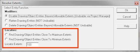
- On the main menu bar, click on [Tools > Resolve Extents].
- Select “Find Drawing/Object Entities Close to Minimum Extents” and then click “Ok.”
- If what appears on the screen is something that does not need to be in the model, delete it and then press the “Plan/Top View” button at the top of the AGi32 dialog.
- If nothing is visible, repeat Steps 1a-1c, above until the lower-left corner of the model/site appears. If the model/site appears but clicking the Plan/Top View button still results in nothing being visible, repeat Steps 1a-1c but this time choose the “Find Drawing/Object Entities Close to Maximum Extents” button to locate extraneous entities.
- Repeat the process described above until clicking the Plan/Top View button shows the model/site.
- Check Scaling: Use the Measure Distance Tool at the top of the AGi32 dialog to measure the distance across an entity with a known dimension (e.g., door, parking space, etc.) and evaluate whether it is the correct size. If it is the correct size, skip to the next step; if not, scrap the import and go back and determine whether the “Units Specified In CAD File” need to be changed or a Scaling Factor needs to be applied when importing the file.
- Check Drawing Coordinates: Look at the coordinates in the lower-left corner of the AGi32 Model Mode screen while moving the mouse around the extents of the imported model/site. If any portion of the model/site is located at coordinates outside of approximately +/- 10000 Feet or Meters, it is strongly recommended that the model’s Origin be moved to avoid future problems. To move the Origin:
- On the main menu bar, click on [Tools > Translate Origin] to initiate the moving of the Origin.
- If the model/site is extremely large, consider moving the Origin to a point in the approximate center of the model/site. If the model is not really large, move the Origin to wherever it makes sense, perhaps somewhere at the southwest corner of what is being evaluated. The goal here is to have everything in the model fall within the +/- 10000-Feet or -Meters coordinate range.
-
Save the AGI file and move forward with the modeling process.
IMPORTANT NOTES:
- When exporting a model back to DWG, the default behavior is for AGi32 to move everything back to the original coordinates in the exported DWG File.
- If it is ever necessary to import a revised background to the original coordinates, make sure to reset the Origin by clicking on the main menu bar [Tools > Reset Translated Origin] before importing the revised background, and then make sure to move (Translate) the Origin again after the revised background has been imported. There is no reason to avoid Translating the Origin when large coordinates are present in a model.
- If issues are encountered while importing into AGi32, please take a look at the Help topic Preparing DWG File for Import.
Importing CAD Files containing 3D Geometry