Modify Luminaire Test Position
This section of the Convert Tool allows you to modify the luminaire test position by applying up to four aiming angles.
Type C:
Type B:
Luminaire Aiming Angles
PTB positions luminaire photometry with respect to the Counterclockwise from East (CCE) system approved and published by the IES in document LM-72-97. All four aiming angles can be applied sequentially to any luminaire and are (in order): Orient, Tilt, Roll, Spin.
The CCE system states that with all four angles equal to zero the luminaire's zero degree plane of photometry is pointing due East. All subsequently applied angles are positive when rotated in a counterclockwise direction.
Application of the aiming angles
The four aiming angles are always applied in succession beginning with Orient, followed by Tilt, then Roll, and finally Spin. Thus, when visualizing a combination of aiming angles, always apply them in order.
Note that all luminaire positions are possible by applying a combination of three aiming angles. The ability to use four aiming angles is simply for ease of operation. Please note that it is also possible to manipulate luminaire position beyond what is possible with conventional mounting hardware.
|
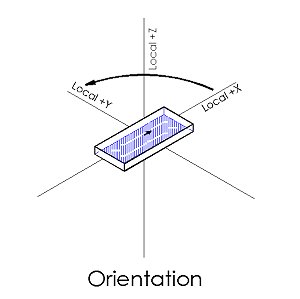
Orient - Orient is applied counterclockwise about the Z-axis. Looking toward -Z, +X axis tends toward +Y. This is a positive Orient angle. Orient=0 places +X due East. Orient is always the first aiming angle applied when multiple aiming angles are specified. Note that before any aiming is applied the Global and Local coordinate systems are aligned. Example: In Plan View (looking down on the luminaire), Orient=0 points the zero degree horizontal plane of photometry due East. Orient=45 is 45 degrees counterclockwise. Typically, for outdoor pole mounted luminaires the zero degree horizontal plane of photometry points out the front of the luminaire. |
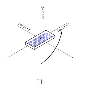
Tilt - Tilt is applied about the local Y-axis. Looking toward +Y, local -Z tends toward local +X. This is positive Tilt. Tilt =0 aligns photometric nadir and zenith with the Z-axis. Tilt is the second aiming angle applied when positioning a luminaire. Example: A Tilt angle of 90 degrees (and Orient=0) will point photometric Nadir due East at the horizon. Likewise, with Orient=90 and Tilt=90 the luminaires photometric Nadir will point North at the horizon. |
|
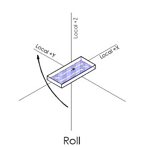
Roll - Roll is applied about the local X-axis. Looking toward -X, local -Z tends toward local +Y. This is a positive Roll angle. The Roll angle is the third aiming angle applied in succession. Example: A Roll angle of 90 degrees when considered with Orient=0 and Tilt=0, will point photometric Nadir due North at the horizon by rolling the luminaire counterclockwise about the X-axis (looking to -X). This effectively stands the luminaire on its side. |
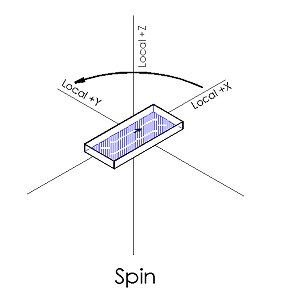
Spin -Spin is applied about the local Z-axis. Looking to -Z, +X tends toward +Y. A positive Spin is then identical to Orient when no other angles are applied. However, once a Tilt or Roll has been applied, the Spin angle operates in the Local coordinate system whereas the Orient angle continues to act Globally. Spin is typically used to rotate the optics within a luminaire assembly. Example: A Spin angle of 45 degrees when considered with Orient=0 and Tilt=45 will Spin the luminaire about the local Z-axis by 45 degrees. The local coordinate system has been tilted by 45 degrees prior to the Spin operation. |