AGi32 Roadway Luminance Calculations With Reflective Surfaces
This topic outlines the procedure and calculation methodology used to consider reflective surfaces in roadway luminance calculations. The primary application of this methodology is tunnel lighting, although it may be applied to other circumstances as well, such as overpasses and signage.
The calculation methodology uses techniques outlined in the IES Recommended Practice for Tunnel Lighting, RP-22-11. The calculations are limited to straight sections of tunnel only and do not consider daylight at this time.

Calculation Method Application
When Full Radiosity Method is enabled, reflective surfaces are considered as reflectors and obstructions. (See specifics below.) When Direct-Only Method is enabled, reflective surfaces are considered as obstructions only; they do not reflect light (only the direct component is used).
Environment Components
Roadway Pavement Surface (RPS):
- Surface Type: 40-Roadway Pavement Surface (Direct Flux Only).
- This surface type is considered in Full Radiosity calculations in these ways:
- Receives and reflects direct flux from luminaires
- Receives reflected light from Roadway Contributing Surfaces (RCS) only
- Reflectance is derived from the Q0 value (R = Q0 * P) for the road surface, as determined by the pavement's r-table classification. Reflectance value is assigned once the roadway grid is specified.
- If roadway calculations are not being performed (no roadway grid), this surface is considered as type 10-Single-Sided and the Direct Flux Only attribute is applied.
- A surface is not necessary in order to perform roadway calculations; the calculation grid can be specified and located independently of any surface.
Roadway Contributing Surface (RCS):
- Surface Type: 41-Roadway Contributor.
- This surface type is considered in Full Radiosity calculations.
- If roadway calculations are not being performed (no roadway grid is placed), this surface is considered as type 10-Single-Sided.
Non-Roadway Surface Types:
- These surfaces will reflect light to the environment but not to roadway calculation grids. (Examples include 11-Double-Sided, etc.)
- Daylight Transition Surfaces are considered according to the table below. Note: daylighting calculations cannot proceed with roadway grids enabled.
Surface Types, Calculation Types, and Roadway Grids:
The following table summarizes the participation of AGi32's various surface types in roadway calculations.
| Surface Type | Calculation Type | Included in Calculation of: | |
|---|---|---|---|
| Model | Roadway Grids | ||
| 10 - Single Sided | Direct Only | Obstructive | Obstructive |
| Radiosity | Obstructive / Reflective | Obstructive | |
| 11 - Double Sided | Direct Only | Obstructive | Obstructive |
| Radiosity | Obstructive / Reflective / Transmissive | Obstructive | |
| 14 - Glass | Direct Only | Obstructive ** | Obstructive ** |
| Radiosity | Transmissive | Obstructive ** | |
| 20 - Daylight Transition Glass (Transparent) | Direct Only | Obstructive ** | Obstructive ** |
| Radiosity | Obstructive / Reflective / Transmissive | Obstructive ** | |
| 21 - Daylight Transition Glass (Diffuse) | Direct Only | Obstructive | Obstructive |
| Radiosity | Obstructive / Reflective / Transmissive | Obstructive | |
| 22 - Daylight Transition Opening | Direct Only | Obstructive | Obstructive |
| Radiosity | Transmissive | Obstructive | |
| 40 - Roadway Pavement (DFO) | Direct Only | Obstructive | Obstructive |
| Radiosity | Obstructive / Reflective | Obstructive / Reflective | |
| 41 - Roadway Contributor | Direct Only | Obstructive | Obstructive |
| Radiosity | Obstructive / Reflective | Obstructive / Reflective (direct component only) | |
| Surface Opening (cut opening with no insert) | Direct Only | Obstructive *** | Obstructive *** |
| Radiosity | Transmissive | Obstructive *** | |
* Cannot consider daylight with Roadway Calculations
** Obstructive if inserted into an opening, ignored if standalone
*** Surface openings are NOT consider in Direct Only or Roadway Calcs (i.e. considered obstructive)
Environment Construction
- Automated:
- Room-Rectangular-Vertical Extrusion – Make Room Into A Roadway Tunnel. When this option is selected, the following changes occur:
- Label = ‘Tunnel’ (default)
- Room has open ends (default)
- Ceiling and walls are specified as Roadway Contributing Surfaces
- Floor is specified as a Roadway Pavement Surface; floor reflectance specified in dialog is ignored. Floor reflectance is based on assigned R-table
- Calculation-Roadway Luminance: Create Roadway Luminance grid in normal fashion
- Manual:
- Construct environment using existing tools (for tunnels, it is recommended to use open ended ‘rooms’)
- Using Surface Edit: Change surfaces to Roadway Pavement Surfaces or Roadway Contributing Surfaces as appropriate. Note: Make sure all surfaces are facing appropriate direction.
- Calculation-Roadway Luminance: Create grid in normal fashion
Calculation Process
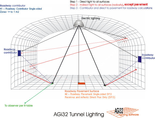
Step 1: Calculating direct component:
- Use existing methodology
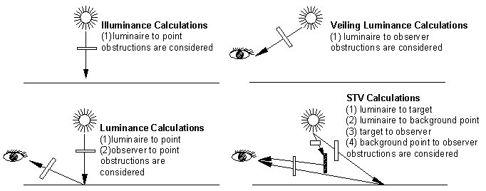
- Obstructions from luminaires to Roadway Pavement Surface and to observer are considered (see graphic below).
- Calculate Full Radiosity solution (Note: This
is different from RP-22, which does not consider a full radiosity calculation):
- When a Roadway Luminance grid is specified, only Roadway Pavement Surface and Roadway Contributing Surface types are used in the radiosity solution; no other surfaces are considered, nor are they visible in Render Mode
- Roadway Contributing Surfaces (RCS) receive direct component from luminaires
- Roadway Pavement Surfaces (RPS) receive direct component
- Obstructions between luminaires and Roadway Contributing
Surfaces, and between Roadway Contributing Surfaces, are also considered (included in normal radiosity calculations)
- Obstructions are considered for these conditions:

Steps 2 & 3: Calculating indirect component
In the second step (Radiosity), the Roadway Pavement Surface reflects the direct light received to the Roadway Contributing Surfaces. The Roadway Contributing Surfaces reflect light to other RCSs, but not to the RPS.
Obstructions from Roadway Contributing Surface to Roadway Pavement Surface are considered, as are obstructions from Roadway Pavement Surface to Observer.
In the third step, all surfaces are assumed to be double-sided; however in Render Mode, Roadway Contributing and Roadway Pavement surfaces are single-sided. In this step, RCSs reflect light to the RPS as follows:
- Break all Roadway Contributing Surfaces into zones (Zone Size £ 1m2). Actual zone size is based on Minimum Surface Dimension (MSD):
- If Minimum Surface Dimension is £ 1m, then Zone Size = MSD2
- If Minimum Surface Dimension is >1m, then Zone Size = (MSD / (Int(MSD) + 1))2. For example: If Minimum Surface Dimension = 25.5m, Zone Size = 25.5/(25+1)2 = 0.98m2
- Calculate exitance (Point Spacing = Zone Size). Automatic Placement points are used
- Using exitance value, calculate intensity Id (cd) reflected by zone to pavement observation point (calculation point).
Formulas
I’ = Lo * Ao
Where:
Lo = Zone luminance = Exitance / p (Lambertian reflection is assumed.)
Ao = Zone size in m2
Id = I’ * Cos(d)
Cos(d) = Cosine of the angle between the normal to the zone surface (direction of I’) and the line from the zone center to the roadway observation point (calculation point) (Lambertian reflection)
Each zone is treated as a luminaire and calculations are completed using existing methodology .