
Ray Tracing - Concepts
Ray tracing is a rendering technique that creates realistic images by simulating the method that light wave rays travel. In AGi32, backwards ray tracing is applied, which means that the rays are traced from the observer position backwards into the scene. For every pixel in the generated Ray Trace image, four rays (or more, depending on the anti-aliasing level) are traced to the corner of each pixel to check for interactions with the objects in each scene. Every time an object is encountered, the color of the surface at that pixel is calculated. If the surface is specular or transmissive, additional secondary rays are traced to determine the contribution of reflected and refracted light and shadows to the final surface color.
In the real world, rays begin at the light sources and are recursively traced from surface to surface, illuminating all the objects in their path. The light reflects and refracts through transparent surfaces over and over again. Only a partial amount enters our eyes or a camera lens. The vast majority of rays never encounter the observer directly, at least in the initial few bounces. Following the rays through this forward ray tracing technique, past the first few bounces, is impractical because it would take an unreasonable amount of time to render the scene and trace the majority of rays back to the observer.
AGi32 allows you to consider both forward ray tracing and backward ray tracing at the same time by selecting the Ray Trace Direct Illumination option in the Ray Tracing Parameters dialog. When this option is chosen, the Number of Bounces selected determines how many recursive (or repeating) rays are traced both forwards and backwards from each object intersection. Be aware, each light source (both the Sun in daylighting and Electric sources) will require a complete set of ray traces through each pixel, so your processing time may increase dramatically. The calculation time is proportional to the number of sources in each environment, regardless of whether they are directly visible in the current scene. Note: This setting is always enabled in daylighting when there is a direct-sun contribution.
The Ray Trace images AGi32 generates are based on the Radiosity calculations AGi32 has previously performed. The Radiosity calculations provide the interreflected flux transfer distribution for the final images. When Ray Tracing is applied to the specified Viewpoint, the Direct component previously calculated in the Radiosity process is removed, and added back to the environment through Ray Tracing.
PseudoColor and Grayscale images may be Ray Traced. If a scale is present in the Render Mode image or in Daylight Study images, it will be included in the Ray Trace image (except HDR images). The scale will be sized according to the size of the ray-trace image and will be placed in the upper-left corner of the image. Note: If the height of the image is less than 365 pixels, the scale may be cut off.
View Dependence
The Ray Trace images generated are view dependent. This is unlike the Radiosity calculation procedure, where you may interactively move through the environment and view all of the surfaces without having to recalculate. In the Radiosity renderings, all surfaces are assumed to be perfectly diffuse (Lambertian), which allows us to view them from any direction as they appear to have the same luminance from any viewing direction. In Ray tracing, surfaces may be diffuse, specular or transparent, and no simplistic assumptions can be made. Ray Trace images have to be independently generated for each viewing location, regardless of the surface reflection or transmission characteristics.
Anti-Aliasing
Anti-Aliasing improves images by removing the jagged edges observed in the final images. Jagged edges occur because of the inherently square shape of each pixel in your display. Lower resolution images have a higher chance of displaying jagged edges because of their lower pixel count. In ray tracing techniques, anti-aliasing is applied by shooting a higher number of rays through each pixel to determine the average color of each pixel.
|
|
|
|
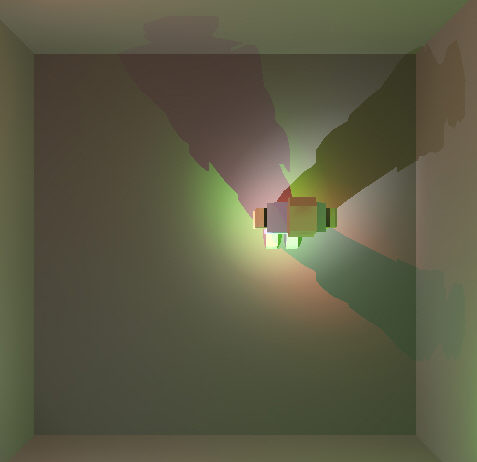
Soft Shadows
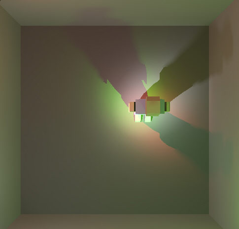
When Ray-tracing the Direct Illumination component, the option to ray-trace Soft shadows is available. Soft shadows are defined as shadows created by light from area sources, or multiple sources and/or directions, causing multiple overlapping shadows and a region of intermediate gray values with 'fuzzy' edges. Soft shadows are intended to produce more realistic ray traced images and are strictly for visual effect. They have absolutely no affect on calculated values. The effects of soft shadows can only be seen in ray traced images. Soft Shadows is a ray trace technique and does not require any changes to the environment. Soft Shadows can increase the number of rays and ray tracing time by an average factor of 10 to 15 times.
Soft Shadows are traced back to the source of direct illumination, regardless of whether the incident surface is specular or diffuse. Soft shadows are created by subdividing the luminous area into 64 equal parts and ray-tracing from each sub-luminaire to the pixel at the point of direct illumination.
For electric lighting, the luminous box representing the luminaire is used as the luminous source. If the luminous box is described as a point source or is small enough to approximate a point source, enabling soft shadows will have little or no effect.
|
Ray Trace Direct Illumination - Soft Shadows not enabled
(Luminous Area assumed to be a point source) |
|
Ray Trace Direct Illumination - Soft Shadows enabled (Luminous
Area 0.3 Ft Diameter) |
For daylighting, the solar corona, apparent in clear and partly cloudy sky models, is used as the luminous source. Soft shadows may be considered in any daylighting environment (daylight exterior surfaces and interior environments attenuated by transition surfaces).The size of the solar corona is assumed and based on empirical measurements.
- If the sky condition is clear (IESNA Clear Sky or CIE Standard Sky 11- 15), AGi32 assumes a solar corona subtending 0.5 degrees.
- If the sky condition is partly cloudy (IESNA Partly Cloudy or CIE Standard Sky 6 – 10), AGi32 assumes a solar corona subtending 2.5 degrees.
|
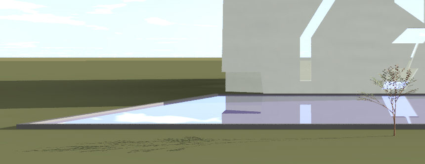
Ray Trace Direct Illumination - Soft Shadows not enabled
(Clear Sky conditions) |
|
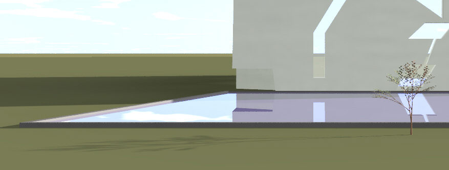
Ray Trace Direct Illumination - Soft Shadows enabled (Clear
Sky conditions) |
The end results of soft shadows may be very subtle and the "bang for the buck" in ensuing calculation times may not be worthwhile for all environments. Soft shadows are most apparent when using larger area sources or when long shadows are present.
Tone Mapping Compression
The human visual system is presented with a vast range of colors and intensities from natural and artificial lighting sources. For example, a starlit night has an average luminance level of around 0.0001 candela/m2, and daylight scenes may be close to 1,000,000 cd/m2. The maximum display luminance is only around 100 cd/m2, which means that our renderings cannot simulate the high dynamic range of naturalistic scenes. The simulation of extreme light and shadow can be reproduced using only the tiny range of available display outputs by applying tone reproduction operators. There are many tone mapping techniques; AGi32 uses the Reinhard tone reproduction method.
The tone mapping compression factor determines the amount of per-pixel highlight luminance compression. If it is set to 1.0, no tone mapping will occur. If it is greater than 1.0, highlights are compressed. If it is less than 1.0, contrast enhancement occurs.
AGi32 uses the following tone mapping compression factors: 1 (no tone mapping or 1 x compression), 2 (2 x compression), 5 (5 x compression), 10 (10 x compression), 0.5 (1/2 x compression), 0.2 (1/5 x compression), and 0.1 (1/10 x compression).
When applying Tone Mapping to environments with daylighting and exterior surfaces, the exposure may need to be adjusted in several ways to make the exterior look correctly exposed. For example, through the Display Properties dialog, one setting may needed to be set to properly display the daylight exterior surfaces, the Exposure increased to make the interior look brighter, and tone mapping applied to ‘tone down' the overexposed exterior.
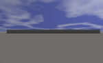
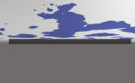
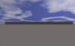
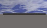
Cloud Images for Daylit Environments
AGi32 allows the user to specify a fractal pattern of clouds superimposed on the sky dome by using a procedural texture technique called Perlin Noise. Perlin noise is a interpolation function that allows us to generate images which vary pseudo-randomly over space and/or time. This technique is often used in computer graphics to make computer-generated objects more natural-looking, by imitating the pseudo-randomness of nature.
Please note the following points regarding cloud images:
- Cloud images are strictly cosmetic and the inclusion of clouds in the sky dome has no effect on the calculated values or surface illuminances/luminances observed in the ray-traced images.
- Cloud images are only available with ray-traced daylit environments and when the Sky Dome is on. Furthermore, cloud images are only visible when the sky dome is visible in the rendered environment.
- Cloud images may be specified automatically or manually.
Automatic Cloud Specification
In the Automatic Cloud Specification images, the Definition parameter is fixed at 0.9 (very defined clouds), the Noise Slice is fixed at 0.6. The Sample Cloud images presented in this dialog may not be representative of the actual cloud imagery ray traced in your environment. The background image behind the cloud fractal is considered also and varies based on the chosen Sky Condition, sun position, solar corona around sun (also derived from Sky Condition algorithms) and surface exposures.
The specified environment luminances and other settings (e.g. Exposure Setting - F/Stop) may have a dramatic effect on the appearance of the clouds. If the sky dome is overexposed, the clouds may not be visible because of their propensity to blend into the background. In general, it is best to select exposure based on daylight surfaces in the Display Properties dialog. If this is not possible, experiment with lowering the Exposure Setting to create more contrast in your images.
Note: These image samples are cropped from a Sky dome looking South East on Sept 12th, 2005 at 10:45 AM with one single sided surface facing the sky dome. The daylight exterior surface exposure is based on one surface (Min and Max luminances are equal). As such, your background color (sky dome background) may not be as vivid as the ones shown in the sample images, because your range of exposure is likely to be much greater and your sky dome will be more overexposed.
|
Sky Condition |
General Description |
Comments |
Sample Images |
||
|---|---|---|---|---|---|
|
General Sky - Type 1, IES Overcast |
Overcast |
maximum coverage - 100%, varying whiteness (1-1.75) |
|
|
|
|
General Sky - Type 2 |
Overcast |
varying high coverage - 92 - 100%, varying whiteness (0.25-2) |
|
|
|
|
General Sky - Type 3 |
Overcast |
varying high coverage - 80 - 92%, varying whiteness (1-2) |
|
|
|
|
General Sky - Type 4 |
Overcast |
varying high coverage - 80 - 92%, varying whiteness (0.25-0.5) |
|
|
|
|
General Sky - Type 5 |
Overcast |
high coverage - 80%, varying whiteness (0.0.5-1.75) |
|
|
|
|
General Sky - Type 6 |
Partly Cloudy |
medium coverage - 68%, varying whiteness (0.25-1) |
|
|
|
|
General Sky - Type 7, IES Partly Cloudy |
Partly Cloudy |
medium coverage - 68%, varying whiteness (1.5-2) |
|
|
|
|
General Sky - Type 8 |
Partly Cloudy |
medium coverage - 56%, varying whiteness (0.25-1.25) |
|
|
|
|
General Sky - Type 9 |
Partly Cloudy |
medium coverage - 44%, varying whiteness (0.25-1.5) |
|
|
|
|
General Sky - Type 10 |
Partly Cloudy |
medium coverage - 44%, varying whiteness (0.5-2) |
|
|
|
|
General Sky - Type 11 |
Clear |
low coverage - 32%, varying whiteness (0.25-2) |
|
|
|
|
General Sky - Type 12 |
Clear |
varying low coverage - 20 - 32%, varying whiteness (0.5-1.5) |
|
|
|
|
General Sky - Type 13 |
Clear |
low coverage - 20%, varying whiteness (0.25-1) |
|
|
|
|
General Sky - Type 14 |
Clear |
very low coverage - 10%, varying whiteness (0.5-2) |
|
|
|
|
General Sky - Type 15, IES Clear Sky |
Clear |
varying low coverage - 10 - 20%, varying whiteness (1.5-2) |
|
|
|


Manual Cloud Specification
The Manual Cloud Specification section allows you to create your own cloud fractals by assigning the cloud generation parameters. Varying the automatic parameters as a starting point will provide more understandable results. The following suggestions give a general overview of the fractal effects.
- To generate ‘stormy’ looking clouds, apply a lower Whiteness parameter
|
Whiteness Value - 0.25
|
Whiteness Value - 0.75
|
Whiteness Value - 1.25
|
Whiteness Value - 2
|

- To generate wispier, less defined clouds, apply a lower Definition parameter
|
Definition Value - 0.1
|
Definition Value - 0.3
|
Definition Value - 0.7
|
Definition Value - 1
|
- To generate a completely different pattern of clouds, modify the Noise Slice (random pattern generation) value. Each decimal value generates a different fractal pattern.
|
Noise Slice Value - 0.1
|
Noise Slice Value - 0.3
|
Noise Slice Value - 0.5
|
Noise Slice Value - 0.7
|
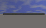
Horizon / Sky Dome size
In Radiosity renderings, the horizon line visible in daylit environments is located in the distance based on the Sky Dome size. It also exhibits a curved appearance because of the finite Sky Dome size. In ray-traced renderings, the horizon line is infinitely far away and the Sky Dome is infinitely large. Therefore, the horizon line no longer appears curved; it is in fact perfectly horizontal and may shift slightly upwards or downwards depending on the eye and focus position. The Sky Dome is also infinitely large, and its extents extend to the edges of the scene for all images.
Ray Trace - Process - (Getting environment ready to Ray Trace)
- Create space in normal fashion (luminaire placement, surface creation, etc.)
- Assign specularity/glossiness to required surfaces using Surface Edit command.
- If Daylighting or Adaptive Subdivision are required, enable these settings.
- Calculate.
- Specify the necessary Ray Trace Parameters.
- In Render mode, specify the desired Views or the desired Viewpoints in one View.
- Start the Ray Trace. Ray Tracing can only be enabled in Render mode.
- View the generated Ray Trace images in the Windows™ Picture and Fax Viewer or My Computer.
How long does it take to generate Ray Trace images?
The time to calculate depends on your hardware makeup, as well as the number of rays shot into the scene. The Ray number is based on screen resolution, space complexity, number of luminaires and amount of specular surface. At the minimum screen resolution AGi32 supports (1024 x 768), one specular surface and no anti-aliasing or direct illumination, the number of rays equals 6,291,456 (over 6 million rays. Most modern computer setups would be able to produce this image in under a minute.
Add anti-aliasing, more specular surfaces and Direct Illumination into the mix, and your calculation times will certainly increase. Consider this worst case scenario: A mirrored room with 100 light sources and anti-aliasing set to 5. There will be 39 rays traced from the camera to each pixel. Each pixel also receive 100 Direct Illumination rays. The rays are then reflected a maximum of 10 times, which produces 390 more ray-surface intersections and another 1,000 Direct Illumination rays. This is 1,529 rays for a single pixel. Multiply this by 1,920,000 pixels for a large bitmap image (1600 x 1200 screen resolution) and total ray count is 2,935,680,000 (that's almost three billion rays). Clearly, this image will require serious calculation time.