
![]()
Object Labeling - Concepts
Text labels for Objects are accessed from the labeling button within any Add or Edit Object dialog. There are three types of labels applied to Objects. Those specific to Objects in general are listed under the Object tab. Labels related to the Component objects when combined into a Library Object (or layers in an imported 3D CAD model) are found under the Component tab. Labels related to the individual surfaces in an object are found under the Component Surfaces tab. Text labels can be placed in your choice of Windows fonts and scaled text size.
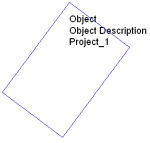
Object Tab
In the example below, an Object with all of the Labeling options from the Object tab is selected. All labels are located below the last vertex point specified when creating the object.
Component Tab
Selecting the Component tab in the Object Labeling dialog presents the selection of text labels relative to the individual objects (or layers in a 3D CAD model) combined to make a Library Object. Selecting this Labeling scheme is only applicable to Library or Imported Objects and will not apply to Objects placed individually.
|
|
|
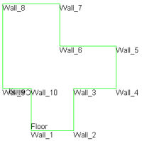
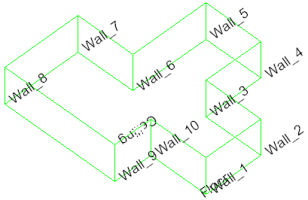
Component Surfaces Tab
Selecting the tab labeled Component Surfaces provides text labels to identify each surface of each component. In the example below left, the image shows the display of Component Surface Labels. The example below, displays Component Surface Reflectances. Depending on the object, these labels can be numerous and may overlap each other. Labels appearing upside down indicate the surfaces are facing away from you. Generally, all labels will be visible if you examine the object from multiple angles. If you plan on using the labels for presentation, you will want to move the obstructed labels with the Move Room Labels command.
|
|
|
Font and Text Size
Text Labels can be applied in any Windows™ font present on your computer system. The default font is set in System Settings. Clicking on the Change button will open the Fonts dialog used to select from your installed fonts. Select your choice of font , font style and color.
Text size is specified in scaled meters or feet in AGi32. This allows convenient scaling of your paper output, as well as legible text labels in the graphics area. Text placed on the drawing at a certain size will remain that size regardless of the output scale. For example, if you place a text label with size equal to five feet, that text will always be five feet tall, regardless if printed at 1" = 20' or 1" = 100'.