

Dynamic Edit - Concepts
Dynamic Editing allows the user to move an edge or node (corner, vertex) of a Room or Object, to remove an existing node, or to add anode to the midpoint on an edge.
Moving an edge allows, for example, the base of a Rectangular Room to be made longer or shorter than it was originally drawn.
As another example, adding a node to the midpoint on one side of a Rectangular Room allows the user to then move than new node to a new location, effectively making the 4-sided Room into a 5-sided Room.

The Add/Remove Nodes command can be used in conjunction with the Move Edge/Node command to manipulate the surfaces of a Room or Object without having to recreate the entity.
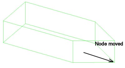
Move an Edge or a Node
When selecting a node (or edge) to be moved, the nodes (or edges) that are directly lined up with it in the View will also be selected. This is 2D editing.
Holding down the Ctrl key on the keyboard enables 3D editing; only the node or edge selected will be affected.
Snap To is automatically set per the command requirements and reset once the command is complete.
- Snap To: On
- Snap To: MidPt, EndPt
- Snap To: Room Object, or RoomObjectOnly (depending on command selected)
- In Plan or Isometric View, the Z coordinate for the cursor must be the same as the point to be selected in order to Snap To the point, unless doing a 3D edit (Ctrl key). This behavior differs from normal Snap To for Plan View.
- In Elevation View, the cursor must be in the same elevation "slice" as the point to be selected in order to Snap To, unless doing a 3D edit (Ctrl key).
The Edit type is determined by the selection:
- Edge: Select MidPt of surface. Selected surface and all attached surfaces are moved.
- Node (2D): Select EndPt of surface. Edge of surfaces(s) attached to node are moved.
- Node (3D): Press Ctrl key and select EndPt. EndPt of surface(s) attached to the node are moved.
In certain cases, the dynamic edit operation will force a surface to be "folded" in order to prevent it from warping. Folding basically splits a 4-sided surface into to two triangles The folded surface takes on the properties of the original surface and is labeled '<SurfaceName>_Fold'.
Warping: A Stop sign icon will be displayed if the attempted Move Edge (or Move Node) edit would result in warped or intersecting surfaces. If this is the case, the command cannot be completed (selected entity is not altered when the command is completed).
Openings: All openings of the selected Object or Room are removed as a result of Move Edge or Move Node editing. Therefore, any inserted objects (such as windows) may be orphaned (no longer inserted into an opening)and should be removed. Because of this behavior, it is best to add Openings after all dynamic editing is complete.
Entity corruption: Move Edge and Move Node editing is a very powerful tool that enables the user to manipulate an entity in ways that may not be physically possible. Consequently, the entity may end up being corrupted. It is recommend that the user make a quick check of the appearance of the edit in Render Mode. If the entity doesn't look right or produces a "parsing error," return to Model Mode and undo (Ctrl-Z)!
Add or Remove a Node
When selecting a node (or edge) to be removed, the nodes (or edges) that are directly lined up with it in the View will also be selected. This is 2D editing.
Holding down the Ctrl key on the keyboard enables 3D editing; only the node selected will be affected.
Snap To is automatically set per the command requirements and reset once the command is complete.
- Snap To: On
- Snap To: MidPt, EndPt
- Snap To: Room Object, or RoomObjectOnly (depending on command selected)
Whether Add or Remove will occur is determined by the selection:
- Add Node: Select MidPt of surface.
- Remove Node: Select EndPt of surface.
Adding a Node
- If the surface is vertical and has four edges (e.g., a Room Wall or an Object Side), the surface is split into two surfaces with the same properties. The new surfaces is labeled '<SurfaceName>_Split'. In addition, a node is added to all attached surfaces (e.g., the floor or ceiling).
- If the surface is non-vertical or does not have four edges, a node is added to the surface and any attached surface sharing the same MidPt (e.g., tilted ceiling surfaces).
- Possible uses:
- Split a Room Wall or an Object Side into multiple surfaces in order to apply different surface properties to each section.
- Add a surface to a Room or Object perimeter in order to modify the perimeter (e.g., add a notch).
- Add a node to a ceiling surface and move the node to achieve a non-standard ceiling shape.
Removing a Node
- If surfaces share the same vertical edge (e.g., Room Walls), one of the surfaces is removed. Removed surface properties depend on surface order, with the surface that remains taking the properties of the one with the lower number. For Rooms, the count is made in a counter-clockwise direction; for Objects, clockwise. The node for any attached surface is also removed (e.g., Ceiling or Floor). Note that for a segmented ceiling, a section of the ceiling may be removed.
- Possible uses:
- Combine surfaces along the same Room Wall or Object Side
- Remove surface from Room or Object perimeter (e.g., remove a notch)
Openings: All openings of the selected Object or Room are removed as a result of Add Node or Remove Node editing. Therefore, any inserted Objects (such as windows) may be orphaned (no longer inserted into an opening) and should be removed. Because of this behavior, it is best to add Openings after all dynamic editing is complete.
Keyboard shortcut: While in the Move Edge/Node command, holding down the Shift key changes the command to Add/Remove Node. Releasing the Shift key changes the command back to Move Edge/Node.