![]()
Rotating Drawing Entities - Concepts
The Rotate Drawing Entity command allows you to rotate drawing entities and text. Drawing entities may be rotated in any view. In North- or South-looking elevation views, the entities are always rotated about the Y axis. In East- or West-looking elevation views, the drawings are rotated about the X axis.
Drawing entities can be rotated by choosing a base point and rotation angle in Plan View or an Elevation View. The specified angle will rotate the selection from a 0-degree orientation around the base point by that angle. Whether the entities are rotated counterclockwise or clockwise depends on the sign of the rotation angle (+/-); (+) is counterclockwise, (- ) is clockwise. The rotation angle may be specified by entering a numeric value or by dragging the mouse to the desired rotation angle.
Example
It is common to import 2D CAD files representing an Elevation View that were created in Plan View in the CAD program. In order to use this background intuitively, we need to rotate it so that it appears in Elevation View. This example illustrates how to do this.
|
Step 1: Original DXF background
|
Step 2: Elevation View taken parallel to X axis
|
|
|
|
|
Step 3: Rotate background in Elevation View to desired angle (270 degrees shown)
|
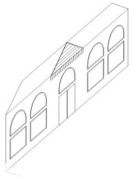
Step 4: Isometric View showing final background rotation
|


