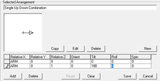
You can create your own custom arrangements easily from scratch or by using an existing arrangement as a template. Factory arrangements cannot be modified but can be copied and subsequently edited and renamed. More information is available in the Luminaire Arrangements topic.
A knowledge of the aiming parameters used in AGi32 is required to apply the appropriate angle modifications.
Copy a Factory Arrangement
- Click on the Factory Arrangement of interest
- Click the Copy button. A copy is made and control moves to the Custom tab where you can make your modifications.
- Cursor focus is on the Arrangement name, enter your own.
- The arrangement's relative coordinate and aiming
information is shown in the right side of the dialog.
- You can edit the existing locations by typing over the information.
- Add additional luminaire lines using the Add button.
- Delete luminaire lines using the Delete button.
- Reset the locations to the original using Reset button.
- Clean all locations using the Clear button.
- Save the arrangement using the Save button.
- Click Ok to exit the dialog with your new arrangement.
Create a new arrangement from scratch
- Click on the Custom tab in the Arrangements dialog.
- Click the New button.
- Enter a unique arrangement name.
- Enter coordinate and aiming information as desired. Each row in the dialog represents a single occurrence of the photometric file. Please see the Arrangement Rules Below) for arrangement variable information and examples.
- Save your arrangement with the Save button.
- Click Ok to exit the dialog with your new arrangement.
Custom Arrangement Examples

|

|

|

|
AGi32 also offers you the option of creating Luminaire Groups, which are different from Arrangements. This can be useful when the components of the arrangement are different luminaires, e.g., a cobrahead and a post-top luminaire on the same pole.
Arrangement Rules
The following rules apply when creating any custom arrangement:
- Arrangement names may be up to 256 characters and may not contain the characters \ / : < > | * ? “.
- To create an arrangement with variable arm length along the orientation angle, use the variable ARM instead of the X and /or Y coordinates. If the variable ARM is found in the custom arrangement, the appropriate input cell (Arm Length) will appear in the Define Luminaire dialog when that arrangement is selected.
Example: Back-to-back
|
X |
Y |
Z |
Orient |
Tilt |
Roll |
Spin |
|
ARM |
0 |
0 |
0 |
0 |
0 |
0 |
|
ARM |
0 |
0 |
180 |
0 |
0 |
0 |
Example: 3 @ 120 degrees
|
X |
Y |
Z |
Orient |
Tilt |
Roll |
Spin |
|
ARM |
0 |
0 |
0 |
0 |
0 |
0 |
|
ARM |
ARM |
0 |
120 * |
0 |
0 |
0 |
|
ARM |
ARM |
0 |
240 * |
0 |
0 |
0 |
* When the arrangement's orientation is not orthogonal (+/- X or +/- Y), ARM should be specified for both X and Y coordinates where ARM in the X direction is specified as ARM * cos(Orient) and ARM in the Y direction is ARM * sin(Orient).
- To create an arrangement with variable arm length perpendicular to the orientation angle, use the variable OFF (or -OFF) instead of the X and /or Y coordinates. OFF is applied perpendicular to the orientation angle (counterclockwise) and -OFF is applied perpendicular to the orientation angle (clockwise). If the variable OFF is found in the custom arrangement, the appropriate input cell (Offset) will appear in the Define Luminaire dialog when that arrangement is selected.
Example: Twin Back-to-back
|
X |
Y |
Z |
Orient |
Tilt |
Roll |
Spin |
|
ARM |
OFF |
0 |
0 |
0 |
0 |
0 |
|
ARM |
-OFF |
0 |
0 |
0 |
0 |
0 |
|
ARM |
OFF |
0 |
180 |
0 |
0 |
0 |
|
ARM |
-OFF |
0 |
180 |
0 |
0 |
0 |