
View 3D Photometric Representation
The 3D tab displays a three dimensional representation of the photometric web that you can rotate and view from any angle.
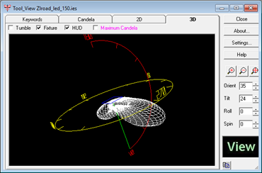
The default view (all angles set to zero) presents an Elevation View looking North (Horizontal Viewing direction) at the 0-180 photometric plane. The zero degree photometric plane points to the right. A Heads Up Display (HUD) is enabled to indicate the photometric testing orientation.
Rotating the Display
The photometric web is rotated by clicking and dragging the mouse in the 3D display.
 Zoom Controls
and Aiming Controls
to manipulate the current view.
Zoom Controls
and Aiming Controls
to manipulate the current view.HUD (Heads Up Display)
The Heads Up Display is enabled in the View Tool by default. Depending on the photometric type being displayed, the HUD will contain various types of information.
Type C Photometry - Nadir is indicated at the bottom of the display (indicated with a 0V notation) and Zenith at the top (indicated with a 180V notation). A red hemicircle runs between the 0 and 180 degree vertical angles in the 0 degree horizontal plane, with hatch marks indicated every 30 degrees. Horizon is indicated with a yellow horizontal circle at the center of the photometric web. Any portion of the photometric web present above this circle indicates uplight, any portion below - downlight. This circle is also hatched into 30 degree horizontal angle increments, with the primary photometric angles indicated every 90 degrees (0, 90, 180 and 270).
Type B Photometry - Nadir is indicated at the bottom of the display (indicated with a 0V notation). Both the vertical and horizontal angular hemicircles run through this point. A red hemicircle runs between the -90 and 90 degree vertical angles in the 0 degree horizontal plane, with hatch marks indicated every 30 degrees. Use this hemicircle to gage the width and symmetry of the lower and upper portions of the beam. A yellow hemicircle runs between the -90 and 90 degree horizontal angles in the 0 degree vertical plane, with hatch marks indicated every 30 degrees. Use this hemicircle to gage the width and symmetry of the left and right portions of the beam.
Fixture
The luminaire shape and size is displayed when this selection is enabled. This information is extracted from the photometric file and assists the user in orienting the photometric web to the luminaire testing position.
Maximum Candela
This option displays the maximum candela locations within the photometric web, indicated by a purple hatch mark. Photometric webs exhibiting quadrilateral or bilateral symmetrical distributions will have multiple maximum candela locations.
Tumble
This selection produces an automatic rotation of the photometric web to show off its shape and orientation. The Tumble Settings are controlled in the View Settings dialog.