
Importing CAD Files - Concepts
AGi32 allows for the import of CAD drawing files in RealDWG (.dwg) and DXF formats from 2012 up to AutoCAD 2018.
Layer Selection
The following layer selection methods are available in both the Import CAD File - Layer Selection tab and the Import Mapping tab:
- Single clicking or clicking and dragging to select one layer or one selection window of layers at one time.
- Shift-select: select adjacent layers and all selection in between top and bottom selections
- Ctrl-select: select non-adjacent layers or non- adjacent selection windows at once.
AGi32 provides four types of layer selection:
- Smart Select Layers - This is the default layer selection method. This method only selects layers that are defined as visible (On and Unfrozen).
- Individual Layer Selection - Layers may be selected individually through toggle selection. AGi32 support the Windows Shift and Ctrl methods for multiple layer selection.
- Select All Layers - This option selects all layers
- Clear Selected Layers - This option deselects all layers.
The Layers selection table only allows for layer selection, it does not provide property control (in other words you cannot switch a layer that is Off to On). These changes may only be applied in a CAD program prior to import in AGi32.
Layers that are selected for import are imported regardless of their properties. If layer selection methods other than Smart Select are employed, the AGi32 file may contain "empty" layers (layers that contain no imported data).
Imported Entity Types
AGi32 will import the following CAD-created entities:
|
Entity |
Comments |
|---|---|
|
Supported Drawing Entity Types:
|
Drawing entity types are never imported as objects. Some drawing entities, such as those with thickness assigned, may look like 3D objects in CAD (they may even shade in CAD), but they are still 2D and will not be converted to objects in AGi32.
Lines, Arcs, LWPolylines, Circles, Trace and 2D Solids with thickness assigned will be imported with defined thickness into AGi32. These are wireframe drawing entities and will not be converted into objects (surfaces) in AGi32.
Mtext formatting is not supported.
Curved 2D entities (e.g., arcs, circles, etc.) will be reconstructed in AGi32 using the specified curve increment. It is recommended that you change the Curve Increment for Import to 5 degrees for exterior background drawings, as these environments typically have shallow curvature lines.
Splines can be imported with Coarse, Medium and High levels of precision. Coarse is the default and s typically adequate for most projects. |
|
Supported Object Types: |
Zero-area and degenerate (self-intersecting) surfaces are not imported. All 3D Faces, Polyface and Polygon Meshes are imported. Non-planar and self-intersecting faces are deconstructed into two planar triangles. All 3D surfaces (planar and non-planar) imported into AGi32 are meshed into planar triangles or quadrilaterals during the import process. |
|
Other Supported Entities (Misc)
|
XREFs are imported automatically if their references can be found. Otherwise, only the master drawing is imported. |
|
Unsupported Entity Types:
|
|
Units and Scaling
Units
AGi32 will read the CAD units setting from the DWG or DXF file and will recognize either the “Engineering” or “Architectural” units settings (both are in inches). All other CAD units settings (decimal, scientific etc.) are assumed to be the same as the current AGi32 units (i.e., if the current AGi32 units are Feet, the imported CAD file is also assumed to be in Feet; if the current AGi32 units are Meters, the imported CAD file is also assumed to be in Meters). In this case it is up to the user to select the correct units, if this assumption is incorrect.
Scaling
An additional Scaling Factor may be applied upon import in addition to any unit conversion scaling. The scaling factor may entered as a decimal value (e.g., 100, 0.75, etc.) or as a fraction (1/2, 7/8, etc.). Math operations are not supported (i.e., +, -, *).
Drawing Extents
The Drawing Extents and drawing location are shown in this section (after Units and Scaling are applied). Drawing Extents displays the minimum extents (LLHC = Lower Left Hand Corner), maximum extents (URHC = Upper Right Hand Corner) and total extents in the selected AGi32 units.
Layers and Blocks
AGi32 imports drawing and object entities on a one-to-one basis. By default, each discreet entity becomes an individual AGi32 entity (either drawing entity or object). Entities are not grouped together into a single object unless specified by the user.
Grouping Drawing Entities
Drawing Entities may be grouped into a single layer in the Miscellaneous section of the Import CAD File dialog. The new Layer Name is specified by the user at this time. Before combining layers, it is important to consider how the CAD file will be used in the job file. Combining the entire file on one layer makes it easy to turn on or off or delete the CAD file; however, it may be desirable to maintain the layers and turn on or off or delete individual layers.
When drawing entities are grouped, all the drawing entities in all selected layers will be combined into one single layer. Drawing entities will retain their individual properties (e.g., color, text formatting, etc.).
Grouping Objects
3D entities may be grouped into a single object in the 3D Import Options section of the Import CAD File dialog. The new Object Name is specified by the user at this time. Each layer is made into an Object Component which may be assigned surface attributes as one definitive grouping. This method of grouping the layers together is only appropriate for entity import (where the imported file represents a single complex entity such as a plant, person, piece of furniture, etc.).
When a whole 3D environment is imported in AGi32, grouping 3D Entities into a single object is strongly discouraged. Complex environments grouped together can cause coplanar surfaces (such as end panels within exterior walls), which may cause calculation errors and abrupt program termination in AGi32.
When 3D entities are grouped, all the objects in all the selected layers will take on the drawing entity properties of the first layer and the surface attributes assigned by default, unless surface mapping is employed.
|
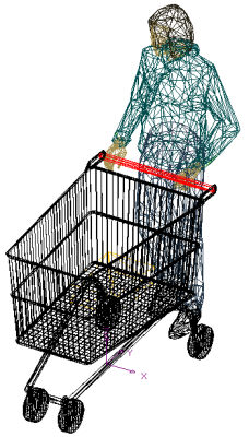
When not grouped together, 3D entity file comes in as 2841 objects. Each object is selectable individually. |
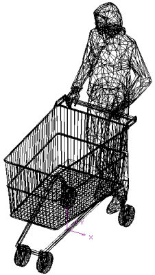
When grouped together, 3D entity file comes in as one object and edited, copied, rotated, etc. as one object. |
Blocks
CAD files support infinitely nested block hierarchies (blocks within blocks within blocks...). However, AGi32 supports only a single level of block 'hierarchy'. The user may select one of three options to convert the potentially infinite hierarchy to a single level:
- Explode all blocks on import (default) - Destroys block hierarchy and uses layer hierarchy instead.
- Keep Low-Level Blocks (only) - Keeps only child blocks (blocks that do not contain any other blocks) intact. All blocks that contain other blocks are exploded. Each exploded entity assumes its properties (color, etc.) based on the layer in which it resides.
- Keep High-Level Blocks (only) - Keeps only parent blocks (blocks that are not contained within any other block) intact. All child blocks contained within the parent block are imported as part of and assume all properties (color, etc.) of the parent block.
Layer/Block Mapping in Project Manager
Project: Each imported CAD file is contained entirely in a new AGi32 project. The import project name consists of the DWG/DXF filename and a date/time stamp.
Drawing Entities: Each layer or block becomes a drawing entity within the Drawing Entity Type classification of the imported project. Color, LineWeight, and LineType are determined by their corresponding entity properties.
Objects: Objects are located within the Object Type classification of the imported project by Object Label. Object Labels are determined by layer or block and the number of objects on that layer or block. Format: LayerName_1, LayerName_2, ... , LayerName_N, BlockName_1, BlockName_2, ... , BlockName_N, etc.
Layer and block names are also preserved in the Component Label of each object.
3D Entities
All 3D surfaces imported into AGi32 are assigned surface properties (such as Color, Reflectance , Texture, etc.). By default, AGi32 imports all 3D surfaces as double-sided surfaces with 50% grayscale reflectance. The surface types and properties may be modified during the import process with import mapping (see below), or after import by using the Surface Edit command.
All 3D surfaces (planar and non-planar) imported into AGi32 are meshed into planar triangles or quadrilaterals during the import process.
The degree to which non-planar (curved) surfaces are meshed can be adjusted in the Advanced Import Options (see below).
Planar surfaces can be merged together. See Coplanar Merging in the Advanced Import Options (below).
Object naming convention
Object Labels are determined by their layer or block name and the number of objects on that layer or block.
Format: LayerName_1, LayerName_2, ... , LayerName_N, BlockName_1, BlockName_2, ... , BlockName_N,etc. (e.g., two objects on Layer Skin would be named Skin_1 and Skin_2).
Layer and block names are also preserved in the Component Label of each object. For example, in a group labeled ImportCar, Layer Wheels would become the name of the Component containing the wheel surfaces,Layer Body would become the name of the Component containing the body surfaces, etc.
Using 3D Entity Models as Library Objects
Composite objects can be saved, to use and reuse, as library objects. Once you save an imported object as a library object, you can reuse it in any job file, complete with its associated material properties.
Note: It is strongly recommended that you create your library objects at a true scale, so that they do not need to be scaled repeatedly with each reuse. We recommend checking the scale of your imported object quickly, in a test file, before you spend a lot of time assigning the desired surface materials.
Entities that are imported as AGi32 objects are assigned surface properties during import. The user can customize these properties by applying an import map. Otherwise, a default import map is used.
Import Maps may be saved and opened. Their location depends on the computer's operating system. In Microsoft Vista, for example, the location is C:\ProgramData\AGi32\Import_Maps. Additionally, an import map is automatically saved for each imported file. If the same file is imported again, the previously saved import map is automatically loaded. Import maps may be deleted by deleting the import map files directly.
Import Filters
- An import map is composed of one or more import filters.
- An import filter is used to apply AGi32 surface properties (such as surface type, reflectance, etc.) to entities with specified CAD properties (color, layer, etc.). Import filters can be thought of as translators that convert CAD properties into AGi32 surface properties. Object properties (component label, wireframe color) cannot be specified by import filters.
- An import filter is applied to each (every) entity and all its sub-entities.
- Only one filter may be applied to each entity (each filter applies an entire set of surface properties).
- If an entity meets the criteria for more than one filter, the entity applies first filter it finds (filter order matters).
- If an entity does not meet the criteria of any filter, the default filter is applied.
Surface Properties (see Surface Edit command for detailed information)
|
Surface Property |
Comment |
|---|---|
|
Surface Label |
Optional surface labels provide for naming objects with consistent name, allowing for easy identification in Project Manager. |
|
Removed |
Selecting this option removes selected surfaces from calculation consideration (surfaces become invisible). |
|
Surface Type |
Available Surface Types: Double Sided, Single Sided, Daylight Transition Glass (Transparent and Diffuse), Daylight Transition Opening, Roadway Pavement Single Sided (Direct Flux Only), and Roadway Contributor Single Sided). |
|
Daylight Exterior |
Selecting this option assigns selected surfaces as Daylight Exterior surfaces (impacts daylighting calculations only). |
|
Color / Reflectance |
Specify a Color / Reflectance value for the selected surfaces. Clicking in this cell results in the Color / Reflectance Selector dialog being displayed. |
|
Texture |
Specify a Texture image to be applied to the selected surfaces. Clicking in the Texture cell opens the Select Texture dialog. A preview thumbnail of the texture is displayed once a texture image is selected. |
|
Transmittance |
Double Sided surfaces may be assigned a diffuse transmittance value (i.e., they behave like frosted glass). |
|
Color / Transparency |
When the Glass surface type is specified, you can specify a Color / Transparency value for the selected surfaces. Clicking in either cell results in the Color / Spectral Radiant Emittance (SRE) Selector dialog being displayed. |
|
Specularity |
Specularity values range between zero and 1, where any value greater than zero results in a high-gloss (shiny) surface in Ray Trace imagery. |
|
Glossiness |
Glossiness values range between zero and 1, where any value other than zero or 1 results in a low gloss finish in Ray Trace imagery. (Must be assigned in conjunction with specularity.) |
|
Color Bleed |
Color Bleed values range between zero and 1, where any value less than one results in less color reflection (used to mitigate saturated color reflection between surfaces for more-realistic appearing renderings). |
|
Mesh Level |
Mesh level changes results in finer or coarser surface discretization for calculations and rendering. (Change from default settings.) |
|
Color / Luminance |
Specify a Luminance value (in Cd/sq.m) for self-emitting surfaces. By default, luminance color equals surface color, but they may be different. Clicking in the Color / Luminance cell results in the Color / Spectral Radiant Emittance (SRE) Selector dialog being displayed. |
|
Direct Flux Only |
Selecting this option assigns selected surfaces as Direct Flux Only surfaces (surfaces receive no reflected light); useful for optimization purposes. |
Default Map/Filter
- Apply to ALL entities ....
- Surface Type : Double-Sided
- Reflectance : 0.5
- Color : RGB - 128 128 128 (middle gray)
Filter Types
- Apply to ALL entities ....
- If Entity has Color ....
- If Entity has LineType ....
- If Entity has LineWeight ....
- If Entity is on Layer ....
- If Entity is within Block ....
- If Entity is on Layer where the Layer Name contains ....
- If Entity is within Block where the Block Name contains ....
Import Mapping tabs
There are two ways to create import maps: by layer and advanced.
By-layer import mapping allows the user to quickly apply surface properties to entities based on the entities' layer (automatically creating layer filters). The CAD Viewer shows a preview of the currently selected layers. To quickly select and clear layers, use the Select All and Clear Selected buttons. Alternatively, you may use the Ctrl-A keystroke combination to toggle the selection between Select All and Clear All.
Advanced import mapping provides more powerful control by providing access to all available filter types. However, the CAD Preview is not updated when creating advanced import maps.
CAD Viewer Usage
- The CAD Viewer allows users to preview a drawing before importing.
- The CAD Viewer responds to layer selection when selecting layers to import as well as selecting layers for import mapping.
- Changing some import options may cause the viewer display to become invalid. Click on the Refresh button in the CAD Viewer to update the display with the new options. The stoplight on the Refresh button will be RED when the viewer needs to be updated and GREEN when the viewer is displaying the current information.
- The CAD Viewer is re-sizable and can overlap the Import CAD File dialog.
Navigation, Tag and View Control Icons
|
Icon |
Command |
Keyboard Shortcut |
Comments |
|---|---|---|---|
|
|
Front View |
|
Displays a Front (South) Elevation View of Object or Room in graphic display. |
|
|
Back |
|
Displays a Back (North) Elevation View of Object or Room in graphic display. |
|
|
Left |
|
Displays a Left (West) Elevation View of Object or Room in graphic display. |
|
|
Right |
|
Displays a Right (East) Elevation View of Object or Room in graphic display. |
|
|
Top |
|
Displays a Top Plan View of Object or Room in graphic display. |
|
|
Bottom |
|
Displays a Bottom Plan View of Object or Room in graphic display. |
|
|
Clip | Cuts away the front plane of the image continuously to reveal the objects within and beyond. The size of the image does not increase or decrease. This command is very useful when viewing an image with exterior and interior components (e.g., interior and site lighting). | |
|
|
Dolly | Moves the observer and the focus point in and out of the model along a straight line. Depending on the view direction, from the observer’s point of view, this feature allows you to “walk” into and out of the space. | |
|
|
Orbit | Moves the observer around the model while maintaining the same focus point. Imagine that you are a spaceship orbiting the earth, always looking at the center of the earth. | |
|
|
Pan | Moves the observer and focus point relative to a fixed model position. Imagine that you are looking straight ahead and moving laterally left/right or up/down. The image will move opposite to the panning direction. | |
|
|
Rotate | Allows the observer to look left or right and up or down from a fixed position. Use this command when you are in a space and want to look at different surfaces without changing your position. A panorama view is obtained by moving constantly to the left or right. | |
|
|
Walk | Combines the Dolly, Pan and Rotate commands into one movement. Dragging the mouse up/down moves the observer forward and backward. Dragging the mouse left/right, rotates the observer view position left and right. Using the Shift and Ctrl keys in conjunction with dragging or the arrow keys invokes the Rotate and Pan commands as well. | |
|
|
Zoom |
Similar to the Zoom In and Zoom Out commands in AGi32’s Model Mode, with the difference being that the image size is continuously increased or decreased as the mouse is held down and dragged. |
|

|
Zoom Extents | Zooms to the extents of the currently selected layers. |
Clicking on the Display Options button below the image opens a list of ways that the image appearance may be modified. For example, you may select to keep outlines visible and surfaces filled in, but not show text or drawing entities associated with this file. In a 3D file, you may also change the Transparency of the model. These selections apply to the image seen in the CAD Viewer only. By default, all options are selected and 3D files are displayed with Transparency = 0% (opaque), with the background color available for modification.
Color Mapping
ACI colors are automatically converted to Windows color numbers. Please note, there are only 256 ACIcolors. Windows uses either; 16, 256, 16-bit or 24-bit colors. Consequently, there may be slight variation in the color between ACI colors and AGi32 colors. New CAD files may have wireframe colors specified using 24-bit colors. AGi32 will be able to match these colors exactly when the file is imported in AGi32.
Line Type Mapping
When importing CAD files into AGi32, CAD linetypes must be mapped to one of AGi32's available line types. The table below shows details of mapping CAD standard linetypes into AGi32.
|
AGi32 Line Type |
ACAD Line Type |
|---|---|
|
SOLID |
CONTINUOUS |
|
DASH |
CENTER CENTER2 CENTERX2 DASHED DASHED2 HIDDEN HIDDEN2 HIDDENX2 PHANTOM PHANTOM2 PHANTOMX2 |
|
DOT |
DOT DOT2 DOTX2 |
|
DASHDOT |
BORDER BORDER2 BORDERX2 DASHDOT DASHDOT2 DASHDOTX2 |
|
DASHDOTDOT |
DIVIDE DIVIDE2 DIVIDEX2 |
All other linetypes are imported as Solid linetypes in AGi32.
Font Mapping
CAD files use their own fonts, and there is no correlation with Windows fonts. Since AGi32 uses Windows fonts, imported text is converted to the current AGi32 default system font. This default font setting is located in the Tools - System Settings dialog and can be changed as desired. Imported text can be changed using the Modify - Drawing - Edit Text command.
Note: If the font described in the imported CAD file is found on the end user's computer (in the Windows Font folder), AGi32 will use the CAD font instead of the AGi32 default system font.
XREF Drawings
External References (XREFs) found in the imported file will automatically be imported if the XREF file can be found.
- 'Clipping' is not supported in XREFs in AGi32. Some CAD programs allow you to 'clip' an XREF with a polygonal boundary so only a portion of the XREF is visible (think viewport). AGi32 imports all entities in the XREF, regardless of what is visible in CAD (i.e., clipping is ignored).
- Another option for including XREFs in the import process is to bind the XREF in CAD.
Binding XREFs
- In CAD, the command BIND is used to bind an external reference (this can be done in the XREF dialog in CAD).
- Binding permanently inserts the XREF as a block into the original drawing. Always do the bind on a copy of the original drawing (so that you do not lose your “live” links).
- You cannot bind XREFs with proxy objects or names with invalid characters.
Text Size and Offset Factors
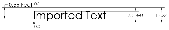
Text Size and Offset Factor are applied to text in DXF files when they are imported into and exported from AGi32. These parameters are applied to the text so that in AGi32 it looks similar to its original appearance in CAD.
The text size in AGi32 determines the size of the character block containing the font glyph and top and bottom leading spaces. In CAD software, the text is created without any top and bottom leading spaces.
|
We have to match this:
|
to this:
|
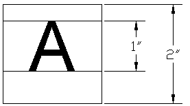
Text Size Factor adjusts the CAD Text Size to correspond to the AGi32 Text Size, which includes the top and bottom leading spaces. An example illustrates these concepts.
- The default Text Size Factor is 2
- AGi32 Text Size = CAD Text Size * Text Size Factor
- AGi32 Text Size = 0.5 * 2 = 1 (used above)
Offset Factor offsets the text to account for the bottom leading space in AGi32.
- The default Offset Factor is 1.5 (1 / 0.66).
- YNEW = Y – (AGi32 Text Size / Offset Factor)
- YNEW = 1 – (1 / 1.5) = 0.33
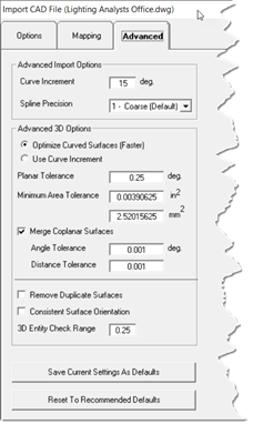
Advanced Import Options
Curve IncrementImported circles, arcs, ellipses, etc. are broken into straight-line segments. A smaller Curve Increment will import the curved geometry more accurately, but at the expense of more line segments. Spline PrecisionImported spline precision can be adjusted between Coarse (default), Medium and High. The default setting is typically adequate. Adjust the setting upward should you find splines not following the CAD created precision. Curved (Non-Planar) Surfaces AGi32 breaks curved 3D surfaces into meshes of planar triangles and quadrilaterals. There are two choices here:
|
|
Planar Tolerance
Many planar surfaces are not exactly planar. this value determines which surfaces are considered to be planar for importing purposes. Surfaces that exceed this value are broken into (planar) triangles or not imported. Larger values will allow more surfaces to be imported, but may adversely affect rendering and calculations.
Minimum Area Tolerance
Surfaces with an area less than the tolerance are considered "null surfaces" and will not be imported. Small surfaces may not be important for calculation purposes (won't affect results), but may significantly slow down the calculation.
Merge Coplanar Surfaces
Many 3D CAD model are (unnecessarily) meshed into triangles and quadrilaterals. Merging these surfaces together can result in drastic improvements in calculation time, display performance, etc. This feature merges surfaces together if:
- The surfaces are coplanar
- The surfaces are adjacent (have a common edge)
Coplanar merging is enabled by default. Check the import summary after importing is complete to see how many surfaces were merged.
Merging coplanar surfaces is tricky business since many surfaces are not exactly coplanar. There are two choices here:
- Angle Tolerance - The maximum angle variance between surface normals for the surfaces to be considered 'coplanar.'
- Distance Tolerance - The maximum distance between surface planes for them to be considered 'coplanar.'
Increasing these tolerances increases the number of surfaces that will potentially be merged together. Merging surfaces that are not actually coplanar can adversely affect rendering and calculations.
Surface Checks
When AGi32 imports 3D entities as objects, they may be inspected for consistent surface orientation and duplicate surfaces. These checks are performed within each object by processing the vertices of a specified percentage of surfaces together within each object. By default, AGi32 uses a value of 0.25 (25%) as its grouping value. This value, the '3D Entity Check Range' may be changed in the Advanced Import Options section of the Import CAD File dialog.
- This process is based on the assumption that adjacent surfaces in the model should be within a certain percentage of each other in the CAD file. This may not always be true, in which case the percentage of surfaces checked should be raised by increasing the '3D Entity Check Range'. A 3D Entity Check Range equal to 1.00 will ensure consistent surface orientation and no duplicate surfaces within each imported object. However, the larger this number, the longer AGi32 will require to perform these inspections and modifications.
- Files with imported surfaces that are of inconsistent surface orientation or have duplicate surfaces may not render with Adaptive Subdivision enabled.